Cooling water flow acquisition method and temperature calculation method for hot-rolled carbon steel laminar cooling jet header

A technology of cooling water flow and cooling spray, applied in the direction of temperature control, workpiece cooling device, metal rolling, etc. The effect of fewer assumptions and simplified conditions, faster calculation speed, and improved control accuracy

Pending Publication Date: 2022-03-15
WISDRI ENG & RES INC LTD
View PDF0 Cites 0 Cited by
  • Summary
  • Abstract
  • Description
  • Claims
  • Application Information

AI Technical Summary

Problems solved by technology

[0005] The purpose of the present invention is to overcome the defects of the prior art, and provide a cooling water flow acquisition method and a temperature calculation method for hot-rolled carbon steel laminar flow cooling injection headers, which are used to solve the problems in the laminar flow cooling process of hot-rolled carbon steel. The preset error of the cooling water flow in the injection header is relatively large, which leads to the problem of low precision of the feedforward control of the temperature of the rolled piece

Method used


Image

  • Cooling water flow acquisition method and temperature calculation method for hot-rolled carbon steel laminar cooling jet header
  • Cooling water flow acquisition method and temperature calculation method for hot-rolled carbon steel laminar cooling jet header
  • Cooling water flow acquisition method and temperature calculation method for hot-rolled carbon steel laminar cooling jet header

Examples


Embodiment 1

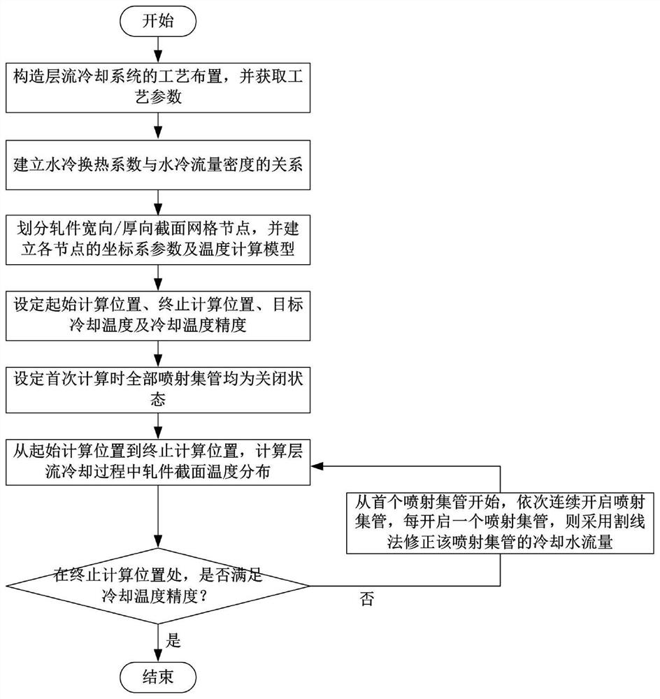
[0102] see figure 1 , the embodiment of the invention provides a cooling water flow acquisition method for hot-rolled carbon steel laminar flow cooling injection header, comprising the following steps:

[0103] S1. Construct the process layout of the laminar flow cooling system, and obtain the process parameters, including the number of spray headers, the center position of each spray header, the spray width, the length of the spray area and the maximum cooling water flow, the thickness, width and speed of the rolled piece , initial temperature and thermophysical parameters.

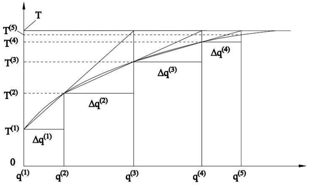
[0104] S2. Establish the relationship between the water-cooling heat transfer coefficient and the water-cooling flow density; the establishment of the relationship between the water-cooling heat transfer coefficient and the water-cooling flow density is obtained by the water-cooling test, and the corresponding water cooling under the corresponding water-cooling flow density is calculated by the linear in...

Embodiment 2

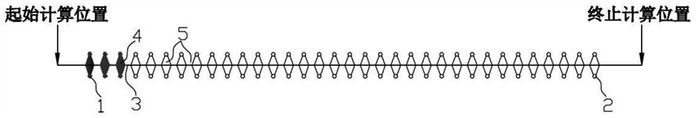
[0174] This embodiment takes hot-rolled low-carbon steel Q235 as an example. On the basis of the method described in Embodiment 1, calculate the preset value of the cooling water flow rate of each spray header in the laminar flow cooling process, and compare it with the actual measured temperature on site. Values ​​are compared to further illustrate the versatility and accuracy of the method of the present invention. The process layout of the laminar flow cooling system is as follows: image 3 As shown, the number of injection headers is 34, and the number from the laminar flow cooling inlet to the outlet is 1# to 34#. The serial number, center position, spray width, spray area length and maximum cooling water flow of each injection header are shown in the table 1 As shown in the first column to the fifth column, the thickness of the rolled piece is 2mm, the width is 1600mm, the initial temperature is 880°C, the thermal conductivity of the rolled piece is 30W / (m×°C), and the s...

Embodiment 3

[0186] The embodiment of the present invention also discloses a method for calculating the laminar flow cooling temperature of hot-rolled strip steel, comprising the following steps:

[0187] Divide the grid nodes of the width-thickness section of the rolled piece, and establish the coordinate system parameters and temperature calculation model of each node;

[0188] Establish the relationship between water-cooling heat transfer coefficient and water-cooling flux density;

[0189] Calculate the water-cooling heat transfer coefficient according to the cooling water flow rate of each injection header set in the laminar cooling process;

[0190] The established temperature calculation model is used to calculate the cross-sectional temperature distribution of the rolled piece during the laminar cooling process.

[0191] Further, divide the grid nodes of the width-thickness section of the rolled piece, and establish the coordinate system parameters and temperature calculation mode...


PUM

PropertyMeasurementUnit
Thicknessaaaaaaaaaa
Densityaaaaaaaaaa

Abstract

The invention relates to a cooling water flow acquisition method and a temperature calculation method for a hot-rolled carbon steel laminar cooling jet header, which adopt a front-section continuous cooling mode, establish a two-dimensional rolled piece temperature field calculation model in a laminar cooling process through theoretical analysis, and calculate the temperature field of a two-dimensional rolled piece on the basis of set laminar cooling process arrangement and a front-section cooling strategy. And according to the established relationship between the water-cooling heat transfer coefficient and the water-cooling flow density, calculating the temperature distribution of the section of the rolled piece by adopting a temperature calculation model, and sequentially correcting the cooling water flow of each injection header by adopting an optimization algorithm according to the difference value between the surface temperature of the rolled piece at the calculation termination position and the target cooling temperature, and the calculated rolled piece temperature is ensured to be consistent with the target temperature. The method is suitable for on-line presetting calculation of the cooling water flow of each injection header in the hot-rolled carbon steel laminar cooling process, so that the temperature of a rolled piece is rapidly and accurately cooled to be close to the nose temperature of a pearlite phase change area, the control precision of the hot-rolled carbon steel laminar cooling temperature is improved, and a pearlite structure is obtained.

Description

technical field [0001] The invention belongs to the technical field of hot rolling, and in particular relates to a cooling water flow acquisition method and a temperature calculation method of a hot-rolled carbon steel laminar flow cooling injection header. Background technique [0002] The laminar flow cooling device is the key equipment to control the cooling temperature of the hot-rolled strip to achieve precise control of the microstructure. Its layout is mainly composed of a certain number of injection headers and control valves. flow, to achieve temperature control of the rolled piece. [0003] The microstructure of hot-rolled carbon steel products is mainly pearlite, and the post-rolling cooling process mainly includes two stages: first, rapid cooling to the "nose temperature" of the pearlite phase transition zone, and then air cooling in the pearlite phase transition zone to the target temperature. cooling temperature. For hot-rolled carbon steel strips of differen...

Claims


Application Information

Patent Timeline
IPC IPC(8): B21B37/76B21B45/02
CPCB21B37/76B21B45/0233B21B45/0218B21B2261/20Y02P70/10
Inventor 陈全忠
Owner WISDRI ENG & RES INC LTD
Why Eureka
Try Eureka