
Support device for fixing tower barrels of various models

A support device and tower tube technology, applied in the field of wind energy, can solve the problems of small application range, not wide application, low work efficiency, etc., and achieve the effects of improving support capacity, moving smoothly, and facilitating installation and disassembly

Pending Publication Date: 2022-03-15
江苏长风海洋装备制造有限公司
View PDF0 Cites 0 Cited by
  • Summary
  • Abstract
  • Description
  • Claims
  • Application Information

AI Technical Summary

Problems solved by technology

[0005] The purpose of the present invention is to provide a bracket device for fixing tower tubes of various types, which solves the problem that the bracket device in the prior art only plays a supporting role, and the bearing bodies on the left and right sides of the bracket device are fixed and can only be used A tower of one size and type has a small scope of application and is not widely used; the tower is placed on the bracket device and cannot be rotated. During the welding process, welders need to weld around the tower, which is time-consuming and labor-intensive, and the work efficiency is high. low problem

Method used


Image

  • Support device for fixing tower barrels of various models
  • Support device for fixing tower barrels of various models
  • Support device for fixing tower barrels of various models

Examples


Embodiment 1

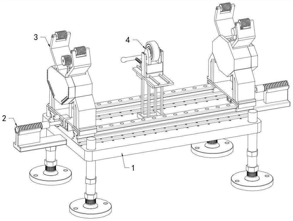
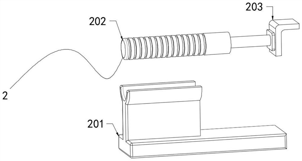
[0034] refer to Figure 1-7 , a bracket device for fixing various types of tower tubes, comprising a bearing part 1, two clamping parts 3 are symmetrically arranged on the top of the bearing part 1, and pushing parts 2 are arranged at both ends of the bearing part 1;

[0035] The bearing part 1 includes a bearing plate 102 arranged horizontally;

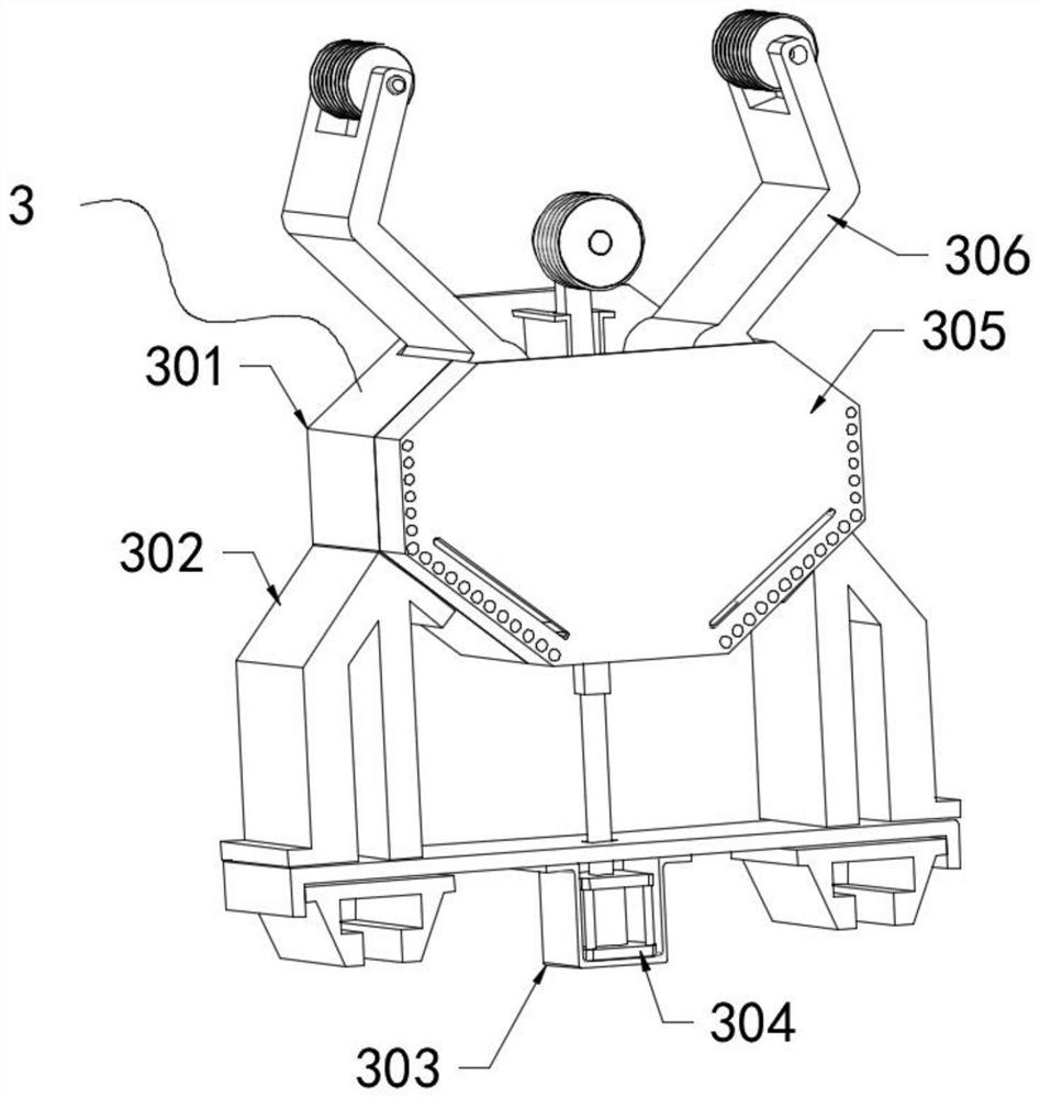
[0036] The clamping part 3 includes an installation bin 301 with an opening at the top, two movable rods 306 arranged symmetrically inside the installation bin 301 , and an adjustment rod 309 arranged between the two movable rods 306 and slidingly connected to the inner wall of the installation bin 301 One end of the two movable rods 306 close to the installation warehouse 301 is fixedly connected with an arc-shaped plate 314, and the ends of the two movable rods 306 far away from the installation warehouse 301 are connected with the side wall of the clamp rod 310 through the clamping rod 310 provided obliquely. Rotate the connected r...

Embodiment 2

[0040] refer to Figure 1-7 One side of the installation warehouse 301 is fixedly connected with a cover plate 305 by bolts, and one side of the cover plate 305 is provided with several connecting holes for the screw to pass through. Fixed plate 308, one end of two brackets 302 is fixedly connected with the top both sides of fixed plate 308 respectively, the top both sides of bearing plate 102 is all fixedly connected with slide rail 103, and the bottom both sides of fixed plate 308 is all fixedly connected with sliding rail 103. The sliding part 307 that the rail 103 is compatible, the top position of an inner wall of the installation warehouse 301 is fixedly connected with the sliding plate 311 that is compatible with the adjustment rod 309, the cylinder 304 is connected with the bottom center of the fixed plate 308 through the base 303, and the cylinder The output end of 304 passes through the fixed plate 308 through the sliding sleeve and is fixedly connected with one end ...

Embodiment 3

[0042] refer to Figure 1-7 The support legs 101 are fixedly connected to the four corners of the bottom of the carrying plate 102, and the support portion 4 is arranged at the center of the top of the carrying plate 102. The support portion 4 includes a horizontal moving plate 407 and two A lifting guide plate 406 symmetrically arranged on both sides of the top of the horizontal moving plate 407, a roller 5 is arranged at the center of the top of the horizontal moving plate 407 and between the two lifting guide plates 406, and the bottom of the roller 5 is provided with two sides and two respectively. The second wedge block 405 that is slidingly connected to the side wall of the lifting guide plate 406 is provided with a wedge block one 404 that is slidably connected to the top of the horizontal moving plate 407 and adapted to the bottom of the second wedge block 405, and both sides of the roller 5 rotate A mounting plate that is fixedly connected to the top of the wedge-shap...


PUM


Abstract

The invention relates to the technical field of wind energy, in particular to a support device for fixing tower barrels of various models, and solves the problems that in the prior art, only one tower barrel of one size model can be applied, the application range is small, and the application range is not wide; the problems that in the welding process, a welding worker needs to weld around the tower drum, time and labor are consumed, the labor intensity is large, and the working efficiency is low are solved. A support device for fixing tower barrels of various models comprises a bearing part, and two clamping parts are symmetrically arranged at the top of the bearing part. According to the device, the structure is reasonable, automatic adjustment can be conveniently achieved, rapid adaptive adjustment can be conducted according to tower barrels with different sizes and specifications and different diameters at the two ends, the tower barrels can be stably supported and can rotate, the use range of the device is widened, meanwhile, the practicability of the device is improved, time and labor are saved during machining, and the machining efficiency is improved. Labor intensity is reduced, and working efficiency is improved.

Description

technical field [0001] The invention relates to the technical field of wind energy, in particular to a bracket device for fixing towers of various types. Background technique [0002] Wind energy is an inexhaustible renewable clean energy. All countries in the world are vigorously developing wind power generation, which has played a positive role in promoting environmental protection and alleviating energy shortages. Wind energy is a clean, safe and renewable green energy. Energy, the use of wind energy has no pollution to the environment, no damage to the ecology, good environmental protection and ecological benefits, and is of great significance to the sustainable development of human society. At present, the technology of the domestic wind power industry is gradually maturing, and wind power towers are widely used in places with sufficient wind energy such as coastal areas, mountains, and plains. China has become the world's largest wind power country. It started late, w...

Claims


Application Information

Patent Timeline
IPC IPC(8): B23K37/053
CPCB23K37/0538B23K37/0533Y02E10/72
Inventor 陈建华张成孙伟伟刘流严善良王柱
Owner 江苏长风海洋装备制造有限公司
Learn More