
Heat treatment equipment for metal processing and manufacturing

A technology for heat treatment equipment and metal processing, applied in heat treatment equipment, heat treatment furnaces, manufacturing tools, etc., which can solve problems such as inconvenient use, lack of adjustment mechanisms in workbenches, and reduced heat treatment efficiency of metal materials, so as to improve practicability and heat treatment efficiency Effect

Inactive Publication Date: 2022-03-15
常德市鼎城区正荣机械制造有限公司
View PDF0 Cites 0 Cited by
  • Summary
  • Abstract
  • Description
  • Claims
  • Application Information

AI Technical Summary

Problems solved by technology

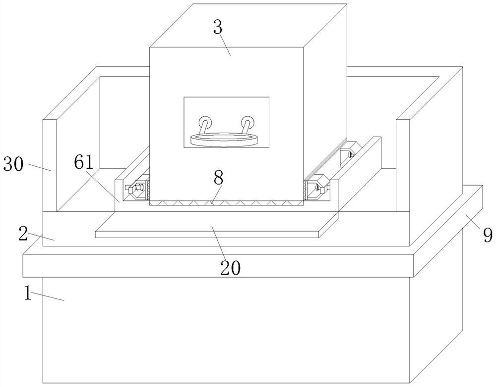
[0006] In order to make up for the deficiencies of the existing technology, the heat treatment machine is often fixedly placed on the workbench for use. During use, because the workbench lacks an adjustment mechanism, the purpose of adjusting the use height cannot be achieved, so that the heat treatment machine is always at a fixed height position. Furthermore, it is extremely inconvenient for operators of different heights to use, thereby reducing the problem of heat treatment efficiency of metal materials. A kind of heat treatment equipment for metal processing and manufacturing proposed by the present invention

Method used


Image

  • Heat treatment equipment for metal processing and manufacturing
  • Heat treatment equipment for metal processing and manufacturing
  • Heat treatment equipment for metal processing and manufacturing

Examples


Embodiment approach

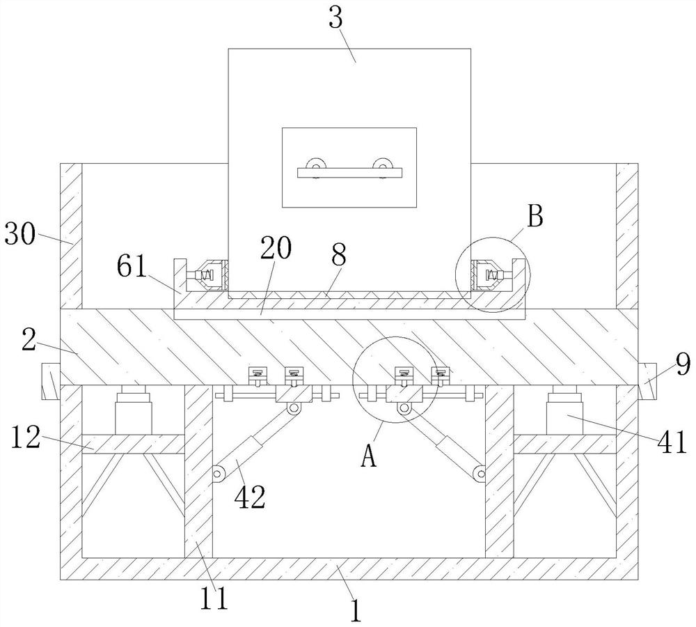
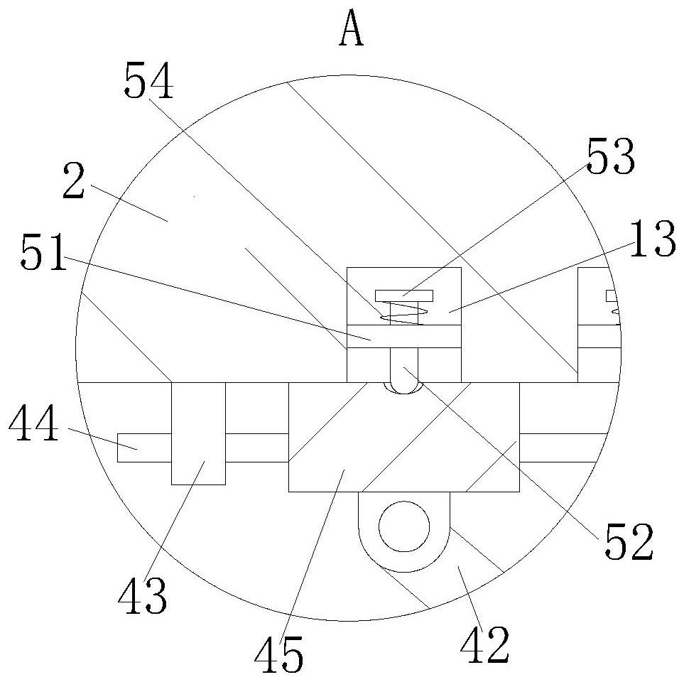
[0028] As an embodiment of the present invention, the inner wall of the bottom of the first workbench 2 is provided with a square groove 13; the inside of the square groove 13 is provided with a clamping assembly; the clamping assembly is in contact with the groove; The connecting assembly includes a bracket 51, an extruding rod 52, a first limit block 53 and a first spring 54; both ends of the bracket 51 are fixed on the side wall of the square groove 13; , and slidingly fit with the inner wall of the bracket 51; the bottom of the extrusion rod 52 is in contact with the groove; the first limit block 53 is fixed on the top of the extrusion rod 52; the first spring 54 is sleeved on the extrusion The outer wall of the top end of the rod 52 ; one end of the first spring 54 is fixedly connected to the bottom of the first limiting block 53 , and the other end is fixedly connected to the top of the bracket 51 .

[0029] During work, when the first workbench 2 lifts the heat treatmen...


PUM


Abstract

The invention discloses heat treatment equipment for metal machining and manufacturing. The heat treatment equipment comprises a base, a first workbench, a heat treatment machine body and an adjusting mechanism. The first workbench is arranged at the top of the base; the heat treatment machine body is arranged at the top of the first workbench; fixing frames are symmetrically arranged in the base; a supporting plate is arranged between the side wall of the fixing frame and the inner wall of the base. The adjusting mechanism is arranged in the base; the adjusting mechanism comprises an electric push rod, a telescopic rod, a fixed block, a sliding rod and a sliding block; the bottom of the electric push rod is fixedly connected to the top of the support plate; the top of the electric push rod is fixedly connected to the bottom of the first workbench. One end of the telescopic rod is hinged to the side wall of the fixed frame, and the other end is hinged to the bottom of the sliding block; and by arranging the adjusting mechanism, a user can conveniently adjust the use height of the heat treatment machine body, so that the heat treatment machine is suitable for operators with different heights to use the machine, and the heat treatment efficiency of the metal materials is improved.

Description

technical field [0001] The invention relates to the technical field of heat treatment, in particular to heat treatment equipment for metal processing and manufacturing. Background technique [0002] Most metal materials exist in the form of solid state in daily life. Common metal materials include gold, silver, copper and iron. Metal materials are heated, kept warm and cooled to improve the performance of metal materials. [0003] For the heating of metal materials, a heat treatment machine is often used for heating. By quickly heating the surface of the metal material, and then immediately removing the metal material for cooling, the performance of the metal material is greatly improved. [0004] The heat treatment machine in the prior art is often fixedly placed on the workbench for use. During use, due to the lack of an adjustment mechanism on the workbench, the purpose of adjusting the height of use cannot be achieved, so that the heat treatment machine is always at a fi...

Claims


Application Information

Patent Timeline
Patent Type & Authority Applications(China)
IPC IPC(8): C21D9/00
CPCC21D9/0006
Inventor 唐金周强代亚烽陈广
Owner 常德市鼎城区正荣机械制造有限公司
Learn More