
Automatic plate arranging machine for electrolytic manganese cathode plates

A cathode plate and automatic discharge technology, which is applied in the field of metallurgical machinery, can solve problems such as inability to push the plates, inconsistent sizes, and confusion of the plates, and achieve the effect of overcoming a large footprint and improving production efficiency

Pending Publication Date: 2022-03-15
宜昌市烨赫机械制造有限公司
View PDF2 Cites 0 Cited by
  • Summary
  • Abstract
  • Description
  • Claims
  • Application Information

AI Technical Summary

Problems solved by technology

There are problems in this way of toggling: one is that the teeth are easy to wear; the other is that the size of the teeth is fixed, and the size of the conductive copper bars on the plate is inconsistent. When encountering thicker conductive copper bars, the teeth will be It cannot be moved; when the conductive copper bars of the adjacent two plates are very thin, it is possible to dial two plates at a time; the third is that there are screws on the conductive copper bars of the plates, and the teeth may be caught on the screws, resulting in extreme board chaos
When there are only a few pole plates or only one pole plate on the conveyor chain, because there is a certain distance between the end of the conveyor chain and the pestle plate, the pestle plate cannot push the pole plate, that is, the device cannot push all the pole plates on the conveyor chain. The plate is pushed out
Furthermore, this patent utilizes the slope at the insertion end of the pestle plate to push, and the pushing force is small, and the effect is not good.

Method used


Image

  • Automatic plate arranging machine for electrolytic manganese cathode plates
  • Automatic plate arranging machine for electrolytic manganese cathode plates
  • Automatic plate arranging machine for electrolytic manganese cathode plates

Examples


Embodiment 1

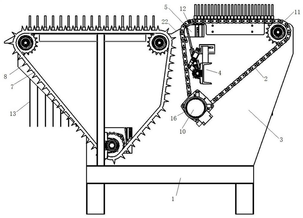
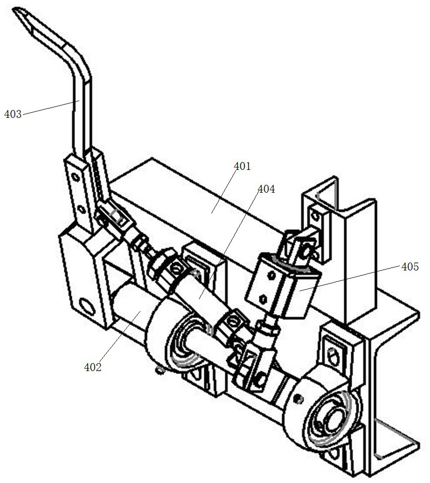
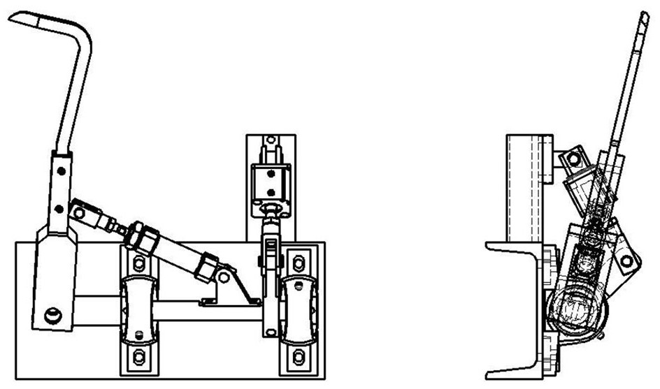
[0029] Such as Figure 1-Figure 10 As shown, an automatic electrolytic manganese cathode plate arranging machine includes a frame 1, which has a plate channel 6, and is symmetrically provided with a transport plate chain 2, a plate opening 5, The driving sprocket 10, the driven sprocket 11 and the chain support, the driven sprocket 11 and the chain support are respectively arranged at the front and rear ends of the pole plate channel side wall 3, and the chain support is arranged above the dial opening 5 . Both sides of the pole plate passage 6 are also provided with a dial device 4, an electromagnetic inductor, a conveying motor 16 and an electromagnetic clutch, and the electromagnetic clutch is connected with the driving sprocket 10 driving the conveying chain. The driving sprocket 10 is connected with the conveying plate motor 16, and drives the conveying plate chain 2 to rotate at a slow speed through transmission mechanisms such as the driving sprocket 10, the driven spr...

Embodiment 2

[0033] Such as Figure 1-Figure 10 As shown, an automatic electrolytic manganese cathode plate arranging machine includes a frame 1, which has a plate channel 6, and is symmetrically provided with a transport plate chain 2, a plate opening 5, The driving sprocket 10, the driven sprocket 11 and the chain support, the driven sprocket 11 and the chain support are respectively arranged at the front and rear ends of the pole plate channel side wall 3, and the chain support is arranged above the dial opening 5 . Both sides of the pole plate passage 6 are also provided with a dial device 4 , an electromagnetic inductor, a conveyer motor 16 and an electromagnetic clutch, and the electromagnetic clutch is connected with the driving sprocket 10 driving the conveyer chain 2 . The conveying plate motor 16 drives the conveying plate chain 2 to rotate at a slow speed through driving mechanisms such as the driving sprocket 10 and the driven sprocket 11 and the chain support. The plate open...


PUM


Abstract

The automatic plate arranging machine is provided with a polar plate channel, polar plate conveying belts, a plate shifting device and a transmission mechanism, the polar plate conveying belts, the plate shifting device and the transmission mechanism are symmetrically arranged on the two sides of the polar plate channel, a plate shifting opening is formed in the side wall of the polar plate channel and located in the polar plate conveying belts rotating circularly, and the plate shifting device shifts polar plates from the plate shifting opening. The non-chain-wheel supporting structure is arranged at the corner of the plate conveying chain, the defect that a chain wheel occupies a large area is overcome, and therefore the plate shifting opening can be formed in the plate conveying chain, and all polar plates on the plate conveying chain can be conveyed to the plate shifting opening when the plate conveying chain rotates; when the plate shifting device shifts the plates from the plate shifting opening, all polar plates on the plate conveying chain can be shifted to the next procedure, continuous operation of the electrolytic manganese post-processing production line is guaranteed, and the production efficiency is improved.

Description

technical field [0001] The invention relates to metallurgical machinery, in particular to an automatic arranging machine for electrolytic manganese cathode plates. Background technique [0002] Electrolytic manganese post-treatment refers to a series of operations for post-electrolytic treatment of electrolytic manganese metal products, including passivation, washing, drying, peeling, packaging, and plate treatment. After the cathode manganese plate is taken out of the passivation pool, it is in a disordered state, and it is difficult to realize the automatic assembly line production of post-processing. In order to realize the automatic assembly line production of post-processing, the cathode manganese plates must be arranged for plate processing. For this reason, Hunan Hongyang Technology Co., Ltd. applied for an invention patent with the authorized announcement number CN102888626 B on October 26, 2012, disclosing an automatic electrolytic manganese cathode plate arranging...

Claims


Application Information

Patent Timeline
IPC IPC(8): C25C1/10C25C7/06
CPCC25C1/10C25C7/06
Inventor 李炜刘正权
Owner 宜昌市烨赫机械制造有限公司
Learn More