
Stationary pile foundation scouring protection structure of offshore wind turbine and construction method of stationary pile foundation scouring protection structure

A technology for offshore wind turbines and protective structures, applied in infrastructure engineering, protective devices, buildings, etc., can solve the problems of high cost, poor effect, and difficult erosion protection, and achieve low manufacturing cost, high environmental friendliness, and meet the requirements of anti-corrosion protection. The effect of flushing demand

Pending Publication Date: 2022-03-15
GUANGDONG MINGYANG WIND POWER IND GRP CO LTD
View PDF0 Cites 0 Cited by
  • Summary
  • Abstract
  • Description
  • Claims
  • Application Information

AI Technical Summary

Problems solved by technology

[0005] The purpose of the present invention is to overcome the deficiencies of the prior art, provide an offshore wind turbine fixed pile foundation scour protection structure and its construction method, and effectively solve the problems of high difficulty, high cost and poor effect of offshore wind turbine pile foundation scour protection

Method used


Image

  • Stationary pile foundation scouring protection structure of offshore wind turbine and construction method of stationary pile foundation scouring protection structure
  • Stationary pile foundation scouring protection structure of offshore wind turbine and construction method of stationary pile foundation scouring protection structure
  • Stationary pile foundation scouring protection structure of offshore wind turbine and construction method of stationary pile foundation scouring protection structure

Examples


Embodiment Construction

[0022] The present invention will be further described below in conjunction with specific examples, but the usage of the present invention is not limited thereto.

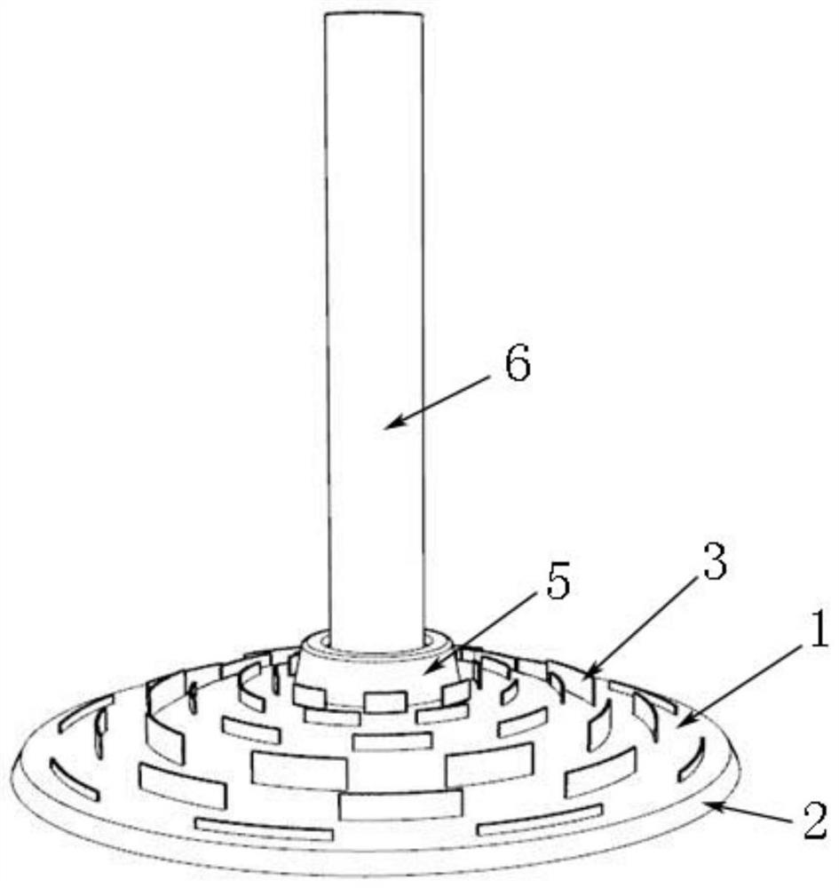
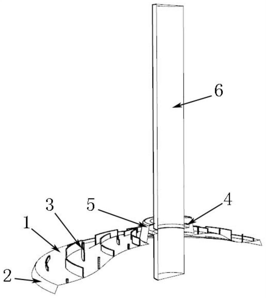
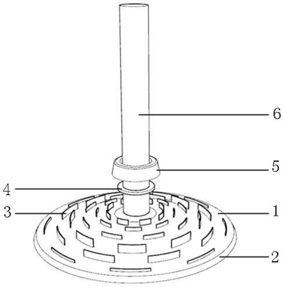
[0023] Such as Figure 1 to Figure 4 As shown, this embodiment provides a fixed pile foundation scour protection structure for offshore wind turbines, including a protective chassis 1, an annular anchor plate 2, a water ladder 3, a fixing ring 4 and a fairing 5; the protective chassis 1 is an inverted plate Shaped structure, the bottom of which fits on the seabed, the outer peripheral edge of the bottom is processed with an annular anchor plate 2 for inserting into the seabed to fix the protective chassis 1, and the top is staggered with several circles of water ladders 3 along the radial direction for blocking and Change the flow direction of the water flow and reduce the starting ability of the water flow to the sediment on the seabed surface. An installation hole 101 for the pile foundation 6 to pass through is ...


PUM


Abstract

The invention discloses an offshore wind turbine fixed pile foundation scouring protection structure and a construction method thereof.The offshore wind turbine fixed pile foundation scouring protection structure comprises a protection chassis, a water ladder, a fixing ring and a fairing, the protection chassis is of an inverted disc-shaped structure, the bottom of the protection chassis is attached to a seabed surface, and an annular anchor plate used for being inserted into a seabed to fix the protection chassis is machined on the peripheral edge of the bottom of the protection chassis; a plurality of circles of water ladders are arranged on the top of the fairing in a staggered mode in the radial direction, a mounting hole allowing the pile foundation to penetrate through is formed in the center of the top of the fairing, the fairing is arranged on the peripheral face of the pile foundation in a sleeving mode through a through hole in the top of the fairing, and the gap between the fairing and the mounting hole is smaller than the gap between the pile foundation and the mounting hole and smaller than the minimum-scale water flow vortex. The fixing ring is arranged on the peripheral face of the pile foundation in a sleeving mode and located between the protection chassis and the fairing, and the fairing is limited to slide towards the seabed through the fixing ring. The problems of large scouring protection difficulty, high cost and poor effect of the fixed pile foundation of the offshore wind turbine can be effectively solved.

Description

technical field [0001] The invention relates to the technical field of offshore wind turbine fixed pile foundations, in particular to an offshore wind turbine fixed pile foundation erosion protection structure and a construction method thereof. Background technique [0002] Offshore wind turbines mostly use pile foundation structures in the form of single piles or jackets. The foundation is hammered deep into the seabed by pile hammers, and plays a role in stabilizing the water surface structure under the mechanical constraints of seabed sand and gravel. The flow environment of the ocean is very complex. The pile-soil structure is always under the joint impact of tides, ocean currents and waves. The flow structure around the foundation is full of eddies with different energy densities, including the horseshoe vortex in front of the pile and the vortex street behind the pile, and Flow acceleration due to the structure itself. The eddy current and accelerated flow increase th...

Claims


Application Information

Patent Timeline
IPC IPC(8): E02D31/06E02D27/42E02D27/12
CPCE02D31/06E02D27/425E02D27/12
Inventor 夏冰邹荔兵吴迪苗得胜张敏刘怀西葛文澎
Owner GUANGDONG MINGYANG WIND POWER IND GRP CO LTD
Learn More