Single crystal material pole diagram pole calibration method based on orientation distribution function
What is AI technical title?
AI technical title is built by Patsnap AI team. It summarizes the technical point description of the patent document.
A technology of distribution functions and single crystal materials, which is applied to the analysis of materials, material analysis using wave/particle radiation, and complex mathematical operations. efficiency effect
Pending Publication Date: 2022-03-15
AVIC BEIJING INST OF AERONAUTICAL MATERIALS
View PDF0 Cites 0 Cited by
Summary
Abstract
Description
Claims
Application Information
AI Technical Summary
This helps you quickly interpret patents by identifying the three key elements:
Problems solved by technology
Method used
Benefits of technology
Problems solved by technology
[0005] Mao Guijiang first determined the azimuth angle of [001] of the material in the article (Residual Stress Test and Analysis of Nickel-based Single Crystal Superalloys with Different Orientations, 2014, Northeastern University) and then carried out stress analysis. However, in the actual stress test process, usually adopt Higher crystal plane index, such as (331), (311), etc., due to the higher crystal plane index and more poles, the current pole calibration method is more complicated
Method used
Image
Click on the blue label to locate the original text in one second.
Reading with bidirectional positioning of images and text.
Examples
Embodiment 1
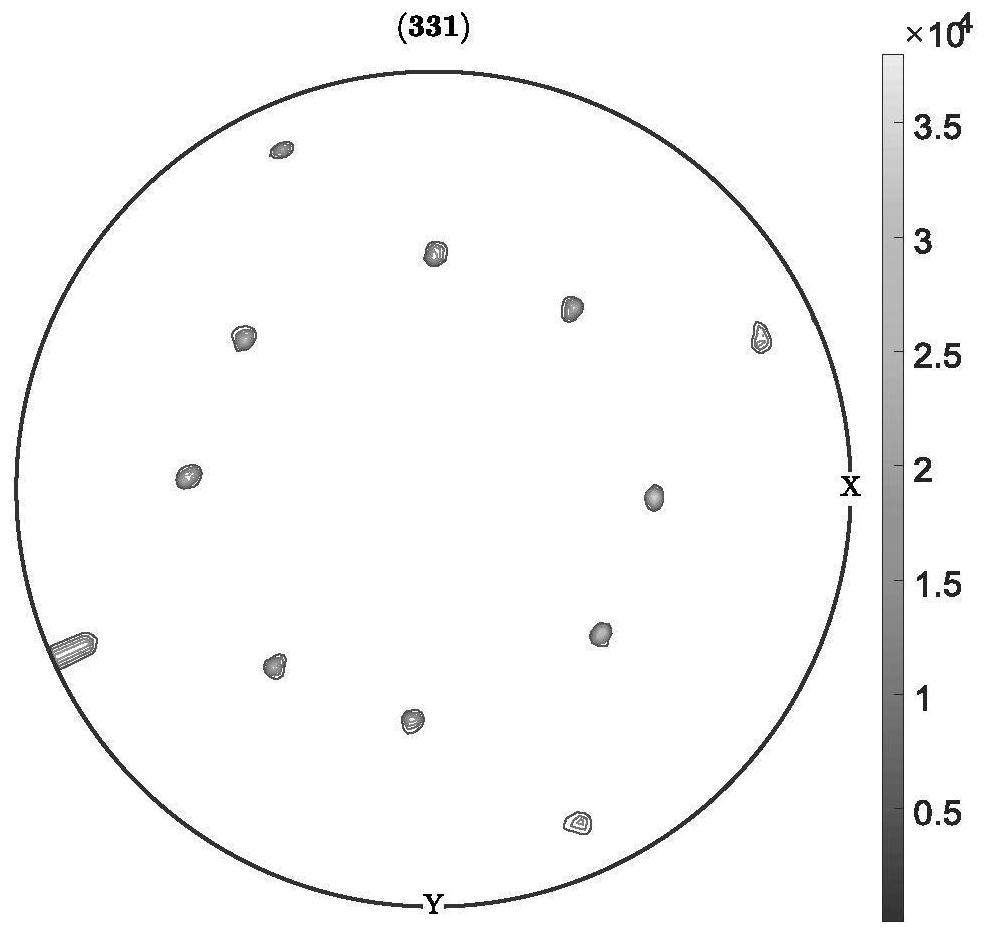
[0055] (1) Put the prepared sample in X-raydiffraction or more, and the test range of 0 to 70 °, the test interval is 2 °, the ψ angle test range 0 ~ 360 ° test interval is 2 °, Take 0.1s of the count time, see attachment figure 1 ;
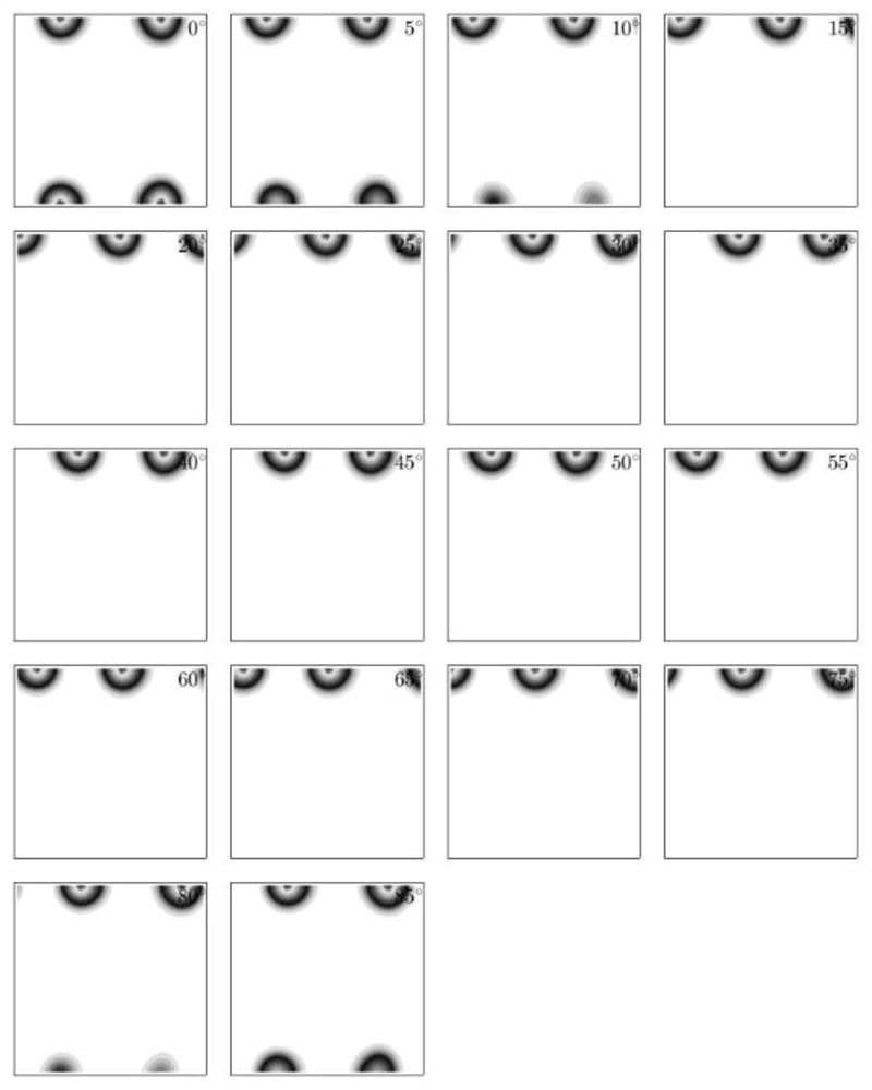
[0056] (2) The material obtained by testing step 1) is measured by the primary map using the Bangure function to calculate the orientation distribution function of the material of 0.1 °.figure 2 ;
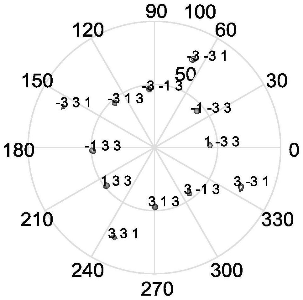
[0057] (3) Using Step 2) The resulting orientation distribution function is calculated, calculate the pole position of each crystal surface of the theoretical position, and corresponding to the measured pole map, complete the calibration of the polar map, see attachment image 3 .
Embodiment 2
[0059] (1) Put the prepared sample in X-raydiffraction or more, and the test range of 0 to 70 °, the test interval is 2 °, the ψ angle test range 0 ~ 360 ° test interval is 2 °, Take 0.1s of the count time, see attachment Figure 4 ;
[0060] (2) The material obtained by testing step 1) is measured by the primary map using the Bangure function to calculate the orientation distribution function of the material of 0.1 °. Figure 5 ;
[0061] (3) Using Step 2) The resulting orientation distribution function is calculated, calculate the pole position of each crystal surface of the theoretical position, and corresponding to the measured pole map, complete the calibration of the polar map, see attachment Image 6 .
Embodiment 3
[0063] (1) Put the prepared sample in X-ray diffraction or more, and the test range of 0 to 70 °, the test interval is 2 °, the ψ angle test range 0 ~ 360 ° test interval is 2 °, Take 0.1s of the count time, see attachment Figure 7 ;
[0064] (2) The material obtained by testing step 1) is measured by the primary map using the Bangure function to calculate the orientation distribution function of the material of 0.1 °. Figure 8 ;
[0065] (3) Using Step 2) The resulting orientation distribution function is calculated, calculate the pole position of each crystal surface of the theoretical position, and corresponding to the measured pole map, complete the calibration of the polar map, see attachment Figure 9 .
PUM
Abstract
The invention discloses a single crystal material pole diagram pole calibration method based on an orientation distribution function, and belongs to the field of pole calibration. The method comprises the following steps: step 1), diffracted intensities of different inclination angles and rotation angles of a test sample are measured to obtain data through a pole density distribution function of the sample, x is a test inclination angle, and psi is a test rotation angle; step 2), calculating an orientation distribution function of the material through a Bonerus function; step 3), listing all crystal face indexes of a test crystal face, and obtaining azimuth angle coordinates of each crystal face through an Euler matrix conversion relation to obtain a theoretical pole diagram of the material; and 4) calculating an error between the theoretical pole diagram and the actually measured pole diagram to obtain a crystal face index of each pole of the actually measured pole diagram. According to the method, the calculation difficulty in the pole calibration process of the single crystal material is greatly simplified, and the calculation efficiency is improved.
Description
Technical field [0001] The present invention is a pole map pole scale calibration method based on the orientation distribution function belongs to the field of pole calibration. Background technique [0002] Single crystal high temperature alloys are generally used for aerospace engine turbine blades, and the blades are harsh, and the material performance is highly required. The direction of the crystal plane is one of the important factors affecting the properties of the material, and its determination is also one of the premise of material performance testing. [0003] Only the crystal surface direction of the respective crystal faces accurately can accurately calculate the residual stress of the surface of the material, thereby optimizing the casting, heat treatment process of single crystal high temperature alloy, and evaluate the safety and reliability of the material. [0004] Chen Yanhua et al (residual stressdiffraction test and analysis, mechanical engineering materials...
Claims
Application Information
Patent Timeline
Application Date:The date an application was filed.
Publication Date:The date a patent or application was officially published.
First Publication Date:The earliest publication date of a patent with the same application number.
Issue Date:Publication date of the patent grant document.
PCT Entry Date:The Entry date of PCT National Phase.
Estimated Expiry Date:The statutory expiry date of a patent right according to the Patent Law, and it is the longest term of protection that the patent right can achieve without the termination of the patent right due to other reasons(Term extension factor has been taken into account ).
Invalid Date:Actual expiry date is based on effective date or publication date of legal transaction data of invalid patent.

