Power transformer cooling device and cooling method

A technology for power transformers and cooling devices, applied in the field of power transformers, can solve problems such as cavitation in negative pressure areas, increase the amount of insulating oil, and bulky volume, and achieve the effects of environmentally friendly cooling and improved cooling efficiency

Pending Publication Date: 2022-03-15
SHAOWU POWER SUPPLY COMPANY OF STATE GRID FUJIAN ELECTRIC POWER +2
View PDF3 Cites 0 Cited by
  • Summary
  • Abstract
  • Description
  • Claims
  • Application Information

AI Technical Summary

Problems solved by technology

[0004] Among the above 4 methods, 1) and 2) have poor cooling effects, and need to rely on over-design and over-manufacturing, greatly increasing the external radiator, increasing the amount of insulating oil, and increasing the volume of the main transformer to meet the normal operation requirements, but even In this way, the cooling effect is still not good
[0005] The third) cooling method, although it can improve the cooling effect to a large extent, but the high-speed operation of the submersible pump with strong oil circulation will cause cavitation in the negative pressure area, and increase the electrification of oil flow, air gap discharge, and submersible The overheating of the oil pump will cause many hazards such as cracking of the surrounding insulating oil. Currently, the main transformer of 220kV and below generally does not use strong oil and strong wind cooling. Strong oil and strong wind circulation cooling method
However, if cooling water leaks into the insulating oil system, even a small water leak will cause disastrous consequences for the high-voltage and high-electric-field operating environment inside the main transformer

Method used


Image

  • Power transformer cooling device and cooling method
  • Power transformer cooling device and cooling method
  • Power transformer cooling device and cooling method

Examples


Embodiment Construction

[0030] In order to make the above features and advantages of the present invention, it is more easightly easy to understand, and the following examples are simultaneously described in detail, but the present invention is not limited thereto.

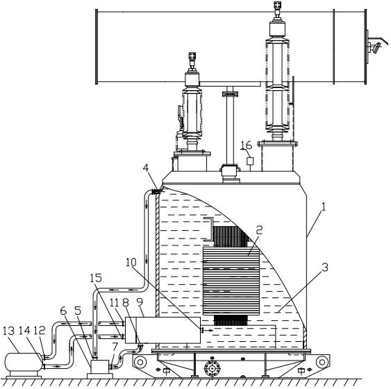
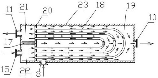
[0031] refer to Figure 1 to 4

[0032] A power transformer cooling device comprising an internal mounting a power transformer body 1 having an insulating oil 3 in which an insulating oil 3 is filled in the electrical transformer body, and an upper portion of the power transformer body is provided. The main shifting the hot oil pipe is connected to the heat-conducting tube 8 of the insulative cylindrical cooler 9 via the inverter circulating oil pump 6, and the insulating barrier cooler is pulled into the lower portion of the lumen of the power transformer body and is provided. The insulating tube 10 is connected to the insulating tube volume cooler having an SF6 variable frequency refrigerator 13, and the upper end of the power transformer b...


PUM


Abstract

The invention relates to a power transformer cooling device and a cooling method.The power transformer cooling device comprises a power transformer body internally provided with a main transformer winding, the power transformer body is filled with insulating oil, and a main transformer hot oil outlet pipe is arranged on the upper portion of the power transformer body; the main transformer hot oil outlet pipe is connected with a hot oil inlet pipe of the insulation cylinder volumetric cooler through the variable-frequency circulating oil pump, the insulation cylinder volumetric cooler penetrates into the lower portion of an inner cavity of the power transformer body and is provided with a cold oil outlet insulation pipe, and the insulation cylinder volumetric cooler is connected with an SF6 variable-frequency refrigerating machine. According to the cooling device, the defects of a traditional main transformer cooling mode are overcome, and the cooling efficiency of the power transformer is greatly improved.

Description

Technical field [0001] The present invention relates to a power transformer cooling device and a cooling method suitable for use in the field of power transformers. Background technique [0002] The existing power transformer cooling technology scheme is as follows: [0003] 1) Natural air cooling; 2) strong wind cooling; 3) strong oil circulation strong wind cooling; 4) Water circulation cooling. [0004] In the above four ways, 1), 2) The cooling effect is poor, and it is necessary to over-design, over-manufacturing, greatly increasing the outer sleeper, increasing the insulating oil, and increasing the maintenance volume, in order to meet the normal operation requirements, even In this way, the cooling effect is still not good. [0005] Part 3), although the cooling effect can be improved to a large extent, the high-speed operation of the strong oil circulation will result in the vaporization of the negative pressure zone, but also increase the oil flow belt electricity, air g...

Claims


Application Information

Patent Timeline
Patent Type & Authority Applications(China)
IPC IPC(8): H01F27/14
CPCH01F27/14
Inventor 林晓铭李丽邓颖黄志勇宋仕江
Owner SHAOWU POWER SUPPLY COMPANY OF STATE GRID FUJIAN ELECTRIC POWER
Why Eureka
Try Eureka