Floor mopping machine

A technology of mopping machine and whole machine, which is applied in the directions of carpet cleaning, floor cleaning, cleaning machinery, etc., can solve problems such as insufficient smooth movement of pallets, increased energy consumption of mopping machines, loss of pallet movement, etc., and achieves enhanced practicability. , reduce work, the effect of smooth motion

Pending Publication Date: 2022-03-18
SHEN ZHEN 3IROBOTICS CO LTD
View PDF7 Cites 0 Cited by
  • Summary
  • Abstract
  • Description
  • Claims
  • Application Information

AI Technical Summary

Problems solved by technology

[0002] In the related art, the supporting plate of the mopping machine is mostly a crank slider mechanism, so that it often needs multiple kinematic pairs to realize the reciprocating linear motion. In particular, there is a large gap between the cam and the supporting plate of the existing reciprocating linear

Method used


Image

  • Floor mopping machine
  • Floor mopping machine
  • Floor mopping machine

Examples


Embodiment Construction

[0042] Embodiments of the present invention will be described in detail below, and examples of the embodiments are illustrated in the drawings, in which the same or similar reference numerals represent the same or similar elements or elements having the same or similar functions. The following is exemplary, and is intended to be illustrative of the invention, not to be construed as limiting the invention.

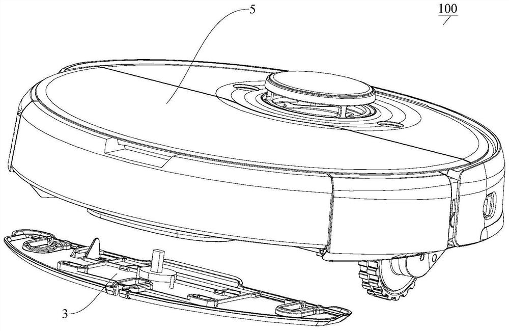
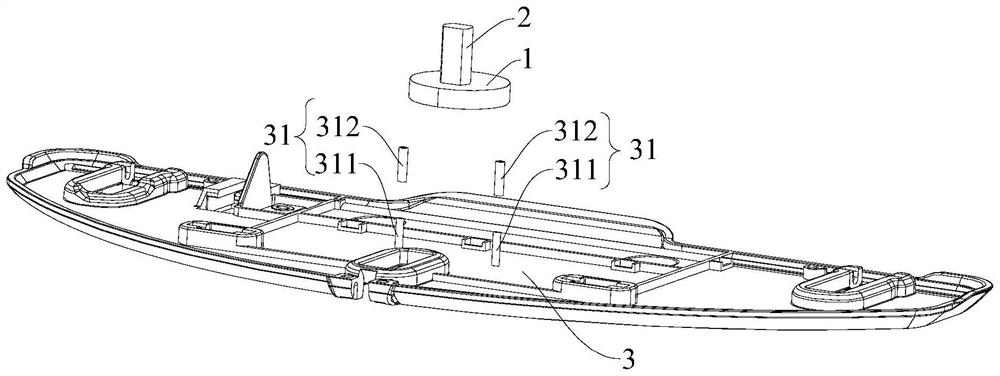
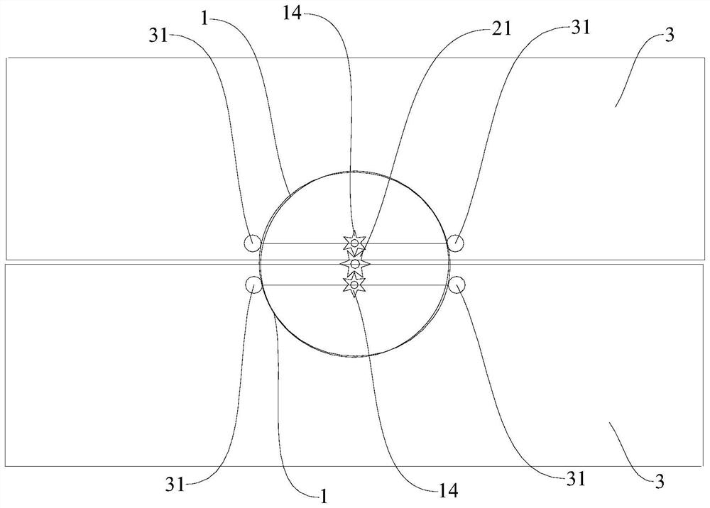
[0043] Below Figure 1 - Figure 11A mollicer 100, according to an embodiment of the present invention, which can be rotated by the drive member 22 simultaneously, and the two cams 11 can be driven by the respective drive unit 31 by the respective drive unit 31. 3 Movement to the backward line, so that the rotational motion of the cam 11 can be converted to the linear movement of the pallet 33 such that the movement of the pallet 33 is more smooth, and it is possible to reduce the work of the pallet 33, and the structure of the cam 11 is simple. Easy to reduce design layout diffi...


PUM


Abstract

The invention discloses a mopping machine which comprises a complete machine, the complete machine is provided with a driving part and two rotatable cams, the lengths of any two line segments, passing through a rotating axis, of the cams on the projection along the corresponding rotating axis are the same, the driving part is in power connection with the two cams, and the driving part is in power connection with the two cams. The two motors are used for driving the two cams to rotate respectively; the two supporting plates are movably mounted on the complete machine, and the two supporting plates correspond to the two cams one to one; each supporting plate is provided with two driving parts, the two driving parts of each supporting plate abut against the two sides of the peripheral wall of the corresponding cam respectively, and the connecting line of the two driving parts of each supporting plate passes through the rotating axis of the corresponding cam. And the cams are suitable for driving the corresponding supporting plates to do reciprocating rectilinear motion through the two driving parts. According to the mopping machine, the rotary motion of the cam can be converted into the linear motion of the supporting plate, so that the motion of the supporting plate is smoother.

Description

Technical field [0001] The present invention relates to the field of household appliances, in particular, involving a mopping machine. Background technique [0002] In the relevant technique, the pallets of the mopping machine are mostly a crank slider mechanism, which often requires multiple movies to achieve reciprocating line motion, especially between the cams and pallets of the existing reciprocating line motion structure. Friction, so that the movement of the pallet is not smooth enough, resulting in moving loss in the pallet, the energy consumption of the mopper is significantly increased, and the structure is complex, the production cost is high, and there is a improved space. Inventive content [0003] The present invention is intended to solve at least one of the technical problems present in the prior art. To this end, an object of the present invention is to propose a mopper, the mopping machine, by providing two cams, and the two cams are rotated around the axis of ...

Claims


Application Information

Patent Timeline
IPC IPC(8): A47L11/284A47L11/40
CPCA47L11/284A47L11/4036A47L11/4069
Inventor 黄忠葵赵坤雷宫海涛杨勇
Owner SHEN ZHEN 3IROBOTICS CO LTD
Why Eureka
Try Eureka