Graphite reaction kettle for hydrogen chloride production

A hydrogen chloride, reactor technology, applied in chemical/physical/physical-chemical stationary reactors, detailed information of chemical/physical/physical-chemical reactors, chemical instruments and methods, etc., can solve the problem of hydrogen chloride gas mixing, mixing uniformity It can reduce the heat loss, improve the mixing quality and save energy.

Pending Publication Date: 2022-03-18
CHINA WANBAO ENG
View PDF1 Cites 0 Cited by
  • Summary
  • Abstract
  • Description
  • Claims
  • Application Information

AI Technical Summary

Problems solved by technology

[0003] The principle of an existing graphite reactor for hydrogen chloride production in the prior art is: the existing hydrogen chloride gas is passed into the reactor through a pipeline and has poor mixing uniformity with the internal material, and the material at the bottom cannot be mixed with the hydrogen chloride gas. Most of the hydrogen chloride gas introduced is at low temperature or normal temperature, which will cause the temperature of the material in the reactor to decrease compared with the previous one, resulting in energy waste

Method used


Image

  • Graphite reaction kettle for hydrogen chloride production
  • Graphite reaction kettle for hydrogen chloride production
  • Graphite reaction kettle for hydrogen chloride production

Examples


Embodiment 1

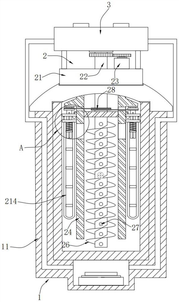
[0017] Please refer to Figure 1-3 , a graphite reactor for hydrogen chloride production, comprising,

[0018] Basic component 1, basic component 1 comprises heat-transfer graphite reactor cylinder 11 and exhaust port, heat-transfer graphite reactor cylinder 11 belongs to the prior art, and the "high-efficiency heat transfer structure of graphite reactor" proposed in the publication number "CN211659989U" "Disclosure, it is composed of steel cylinder, supporting feet, graphite cylinder, combustion box, combustion chamber, air hole, exhaust pipe, heating chamber, burner, hot water tank, circulating water pump and other structures, and will not be described in detail here. As mentioned above, the outer wall of the heat transfer graphite reaction cylinder 11 is also provided with a discharge port and a feed inlet, both of which are not shown in the figure, and the left and right sides of the heat transfer type graphite reaction cylinder 11 are provided with exhaust ports for disch...

Embodiment 2

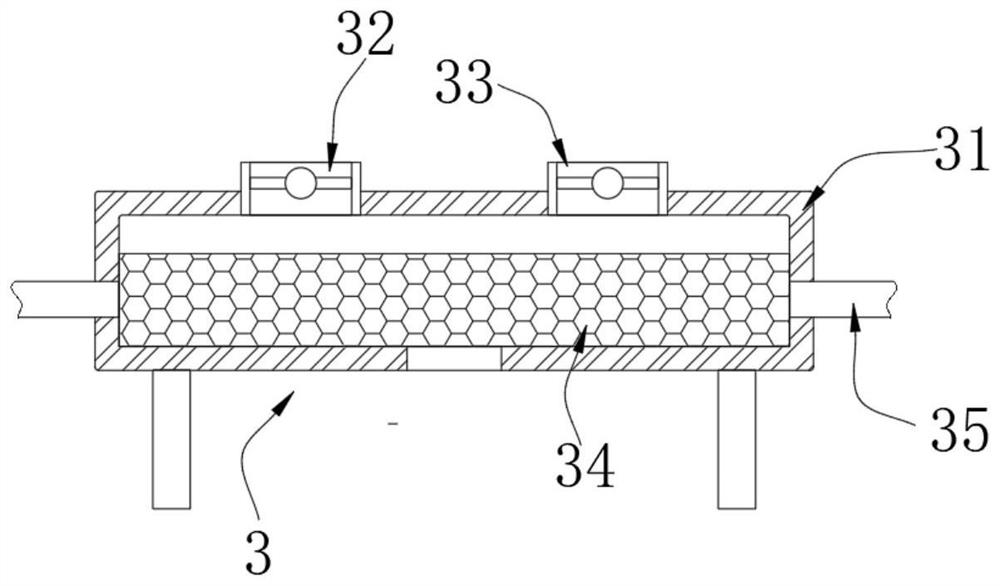
[0026] Please refer to image 3 As shown, the air intake assembly 3 includes an air intake shell 31 that is arranged on the top of the support base 21 through a bracket, and the left and right sides of the top of the air intake shell 31 are respectively provided with an air intake pipe 32 and an exhaust pipe 33 that communicate with each other, and the exhaust pipe 33 It is used to exhaust the hot gas and flue gas produced by combustion. The intake pipe 32 allows the hydrogen chloride gas to enter, and the intake pipe 32 and the exhaust pipe 33 are equipped with solenoid valves to facilitate the control of the opening and closing of the intake and outlet. Two sets of exhaust ports The other ends are connected with a connecting air pipe 35, and the other end of the connecting air pipe 35 communicates with the bottom of the side wall of the air intake shell 31. The connecting air pipe 35 allows the hot gas and smoke generated by combustion to enter the air intake shell 31, and th...


PUM


Abstract

The present invention provides a graphite reaction kettle for hydrogen chloride production, which comprises: a base assembly, which comprises a heat transfer type graphite reaction cylinder and an exhaust port; the mixing assembly comprises a supporting seat fixedly embedded in the top of the cover plate, a hollow shaft movably penetrates through the middle of the supporting seat up and down, a spiral blade is arranged at the position, below the base plate, of the outer wall of the hollow shaft, and a plurality of sets of seepage holes are formed in the position, below the base plate, of the circumferential outer wall of the hollow shaft at equal intervals from top to bottom; and the air inlet assembly comprises an air inlet assembly which is arranged at the top of the supporting seat through a bracket. The mixing assembly is arranged, the hollow shaft rotates through the driving device and the gear set, then materials circularly flow from bottom to top through the spiral blades, hydrogen chloride gas seeps out of the seepage holes, the materials and the hydrogen chloride gas are evenly mixed, and the reaction quality is improved.

Description

technical field [0001] The invention belongs to the field of graphite reactors, in particular to a graphite reactor for hydrogen chloride production. Background technique [0002] In chemical production, some materials need to pass hydrogen chloride into the reaction kettle to participate in the synthesis when reacting in the graphite reactor. [0003] The principle of an existing graphite reactor for hydrogen chloride production in the prior art is: the existing hydrogen chloride gas is passed into the reactor through a pipeline and has poor mixing uniformity with the internal material, and the material at the bottom cannot be mixed with the hydrogen chloride gas. Most of the hydrogen chloride gas introduced is at low temperature or normal temperature, which will cause the material temperature in the reactor to decrease compared with before, resulting in energy waste. Contents of the invention [0004] In view of the above-mentioned defects or deficiencies in the prior a...

Claims


Application Information

Patent Timeline
Patent Type & Authority Applications(China)
IPC IPC(8): B01J19/18B01J19/00B01J4/00
CPCB01J19/18B01J19/0066B01J19/006B01J4/001B01J2219/00768B01J2204/002
Inventor 姜鲲余跃海齐书元刘松蔡航清赵越杨小雨刘剑超张圣辉
Owner CHINA WANBAO ENG
Why Eureka
Try Eureka