Gate driving method, gate driving circuit and display

A gate drive circuit and gate drive technology, applied in the electronic field, can solve the problems of high cost, complex drive structure, and low resolution, and achieve the effects of small structure size, simplified gate drive structure, and low resolution

Active Publication Date: 2022-03-18
CHONGQING HKC OPTOELECTRONICS TECH CO LTD +1
View PDF8 Cites 0 Cited by
  • Summary
  • Abstract
  • Description
  • Claims
  • Application Information

AI Technical Summary

Problems solved by technology

[0004] The gate drive method, gate drive circuit and display provided by the present invention solve the problem of complex drive structure and high cost in the prior art, and simplify the The driving structure and driving method reduce the driving cost and meet the needs of liquid crystal displays with low resolution, small structure size and display samples.

Method used


Image

  • Gate driving method, gate driving circuit and display
  • Gate driving method, gate driving circuit and display
  • Gate driving method, gate driving circuit and display

Examples


Embodiment 1

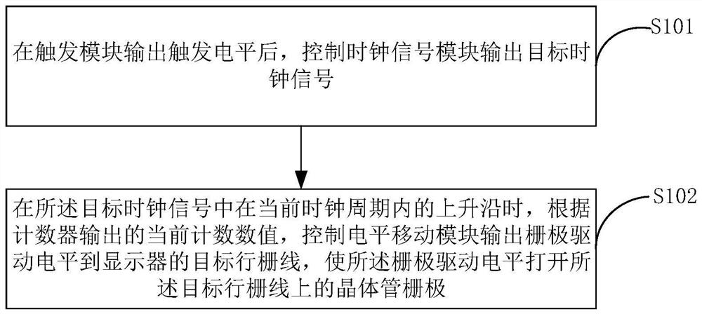
[0033] figure 1 Shown is a schematic flowchart of a gate driving method provided by an embodiment of the present invention, as shown in figure 1 As shown, the gate driving method specifically includes the following steps:

[0034] Step S101, after the trigger module outputs the trigger level, control the clock signal module to output the target clock signal.

[0035] In this embodiment, after the trigger module outputs the trigger level and before controlling the clock signal module to output the target clock signal, the driving method further includes: obtaining the total number of clock cycles in the clock signal according to the number of row gate lines of the display ; Obtain the clock cycle duty ratio according to the frame rate of the display; make the clock signal module generate the target clock signal according to the total number of clock cycles and the clock cycle duty ratio.

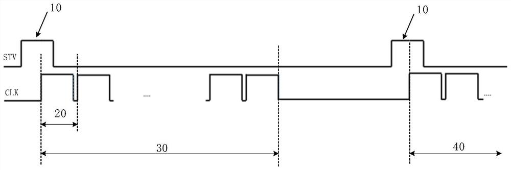
[0036] It should be noted that, if figure 2As shown, the output of the trigger module...

Embodiment 2

[0048] In this embodiment, when the gate drive circuit includes at least two level shifting modules, the drive method further includes:

[0049] On the falling edge of the last clock cycle of the first target clock signal, the clock signal module is controlled to output a second target clock signal, so that the target level shift module performs gate driving according to the second target clock signal; wherein, The first target clock signal is the target clock signal output by the clock signal module at the current clock signal port, and the second target clock signal is the target clock signal output by the next clock output port of the current clock output port, The target level shifting module is a level shifting module connected to the second target clock signal output port.

[0050] It should be noted that when the number of output terminals of the level shifting module is less than the number of row gate lines of the display, multiple level shifting modules are required ...

Embodiment 3

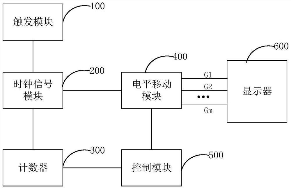
[0056] image 3 Shown is a schematic structural diagram of a gate drive circuit provided by an embodiment of the present invention; image 3 As shown, the gate drive circuit includes:

[0057] A trigger module 100, configured to output a trigger level;

[0058] A clock signal module 200, configured to output a target clock signal;

[0059] The counter 300 is configured to start counting on the rising edge of the first clock cycle in the target clock signal, and clear to zero on the falling edge of the last clock cycle in the target clock signal;

[0060] Level shifting module 400, the input end of level shifting module 400 is connected with described clock signal module 200, a plurality of output ends of described level shifting module 400 are respectively connected with a plurality of row gate lines of display 600 one by one, with To sequentially output the gate drive level to each row gate line of the display, so that the gate drive level sequentially turns on the transis...


PUM


Abstract

The invention relates to a gate driving method, a gate driving circuit and a display, and the driving method comprises the steps: controlling a clock signal module to output a target clock signal after a trigger module outputs a trigger level; when the target clock signal is at a rising edge in a current clock period, according to a current counting value output by a counter, controlling a level shifting module to output a gate driving level to a target row gate line of the display, so that the gate driving level opens a transistor gate on the target row gate line; wherein the counter is reset at the falling edge of the last clock period in the target clock signal, and recounts at the rising edge of the first clock period in the next target clock signal; the problems of complex driving structure and high cost in the prior art are solved, the driving structure and the driving mode are simplified, the driving cost is reduced, and the requirements of liquid crystal displays with low resolution, small structural size, sample display and the like are met.

Description

technical field [0001] The invention relates to the field of electronic technology, in particular to a grid driving method, a grid driving circuit and a display. Background technique [0002] In the prior art, a thin film field effect transistor (Thin Film Transistor, TFT for short) is integrated on the array substrate by using Gate Driver on Array (GOA for short) technology to control the gate lines in the display panel. Scan driving, so that the part of the gate driver IC can be saved, which is conducive to the realization of narrow borders. [0003] However, for specific liquid crystal displays such as low resolution, small structure size and display samples, there are problems such as complex driving structure and high cost when using GOA technology for gate driving, which does not meet the driving requirements of specific liquid crystal displays. Contents of the invention [0004] The gate drive method, gate drive circuit and display provided by the present invention...

Claims


Application Information

Patent Timeline
Patent Type & Authority Applications(China)
IPC IPC(8): G09G3/36
CPCG09G3/3677
Inventor 周满城熊志康报虹
Owner CHONGQING HKC OPTOELECTRONICS TECH CO LTD
Why Eureka
Try Eureka