Wafer transfer position adjusting method and device

An adjustment method and an adjustment device technology, which are applied in image data processing, instruments, electrical components, etc., can solve the problems of wafer transfer position adjustment, affecting the uniformity of the wafer, and can only be carried out under normal temperature conditions. Achieve the effect of improving the uniformity in the chip and improving the heating effect

Pending Publication Date: 2022-03-18
PIOTECH CO LTD
View PDF0 Cites 2 Cited by
  • Summary
  • Abstract
  • Description
  • Claims
  • Application Information

AI Technical Summary

Problems solved by technology

[0002] In the wafer processing process, the common path for transferring wafers includes the equipment front-end module (Equipment FrontEnd Module, EFEM), vacuum lock (load lock, LL) chamber assembly, wafer transfer module (Transfer Module, TM) and process Module (process module, PM), after the wafer is transferred from the wafer transfer module to the process module, it is necessary to carry out wafer transfer calibration for each position of the wafer, so as to ensure that each time the wafer enters the process module after passing through the manipulator. Inside the chamber, after the positioning device is placed on the heater, it is just placed in the center of the heater, but this calibration can only be performed under normal temperature conditions. Under normal temperature and vacuum conditions, after adjusting the film transfer position, open the cavity. Wafer confirmation, whether it is aligned with the center of the heating plate
However, under high-temperature heating conditions, since the heating chamber cannot be opened, it is impossible to accurately obtain whether the position of the wafer on the heating plate is accurate, so that the position of the wafer transfer cannot be adjusted, thereby affecting the wafer heating effect. , affecting the on-chip uniformity of wafer processing

Method used

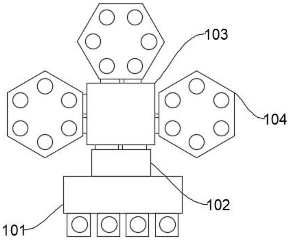
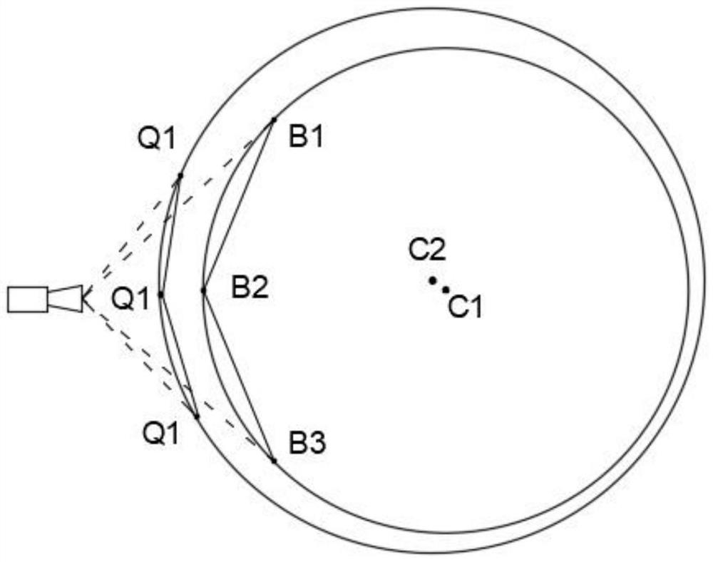

Image

  • Wafer transfer position adjusting method and device
  • Wafer transfer position adjusting method and device
  • Wafer transfer position adjusting method and device

Examples


Embodiment Construction

[0044] In order to make the purpose, technical solutions and advantages of the present invention clearer, the technical solutions in the embodiments of the present invention will be clearly and completely described below in conjunction with the accompanying drawings of the present invention. Obviously, the described embodiments are part of the present invention Examples, not all examples. Based on the embodiments of the present invention, all other embodiments obtained by persons of ordinary skill in the art without creative efforts fall within the protection scope of the present invention. Unless otherwise defined, the technical terms or scientific terms used herein shall have the usual meanings understood by those skilled in the art to which the present invention belongs. As used herein, "comprising" and similar words mean that the elements or items appearing before the word include the elements or items listed after the word and their equivalents, without excluding other el...


PUM


Abstract

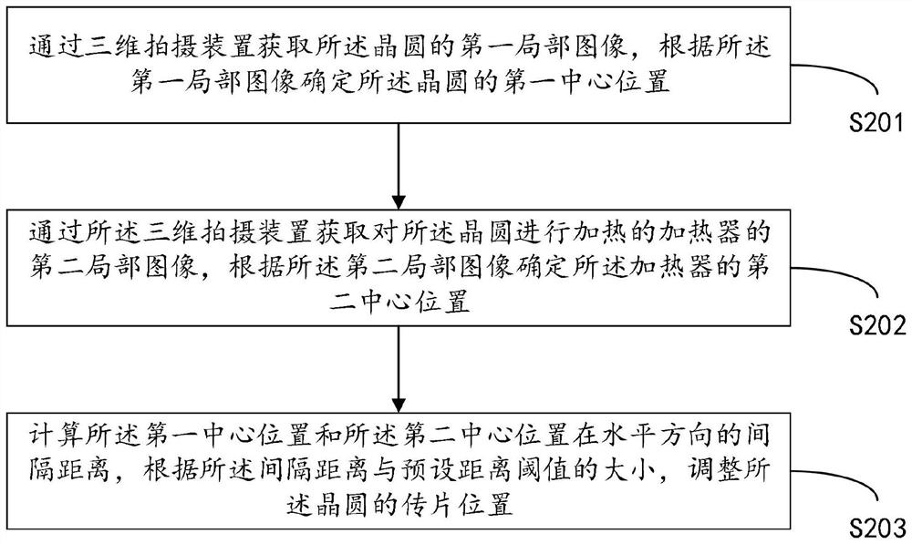
The invention provides a wafer transfer position adjusting method and device, which are applied to the heating process of a wafer, and the adjusting method comprises the steps: obtaining a first local image of the wafer through a three-dimensional shooting device, and determining a first central position of the wafer according to the first local image; acquiring a second local image of a heater for heating the wafer through the three-dimensional shooting device, and determining a second central position of the heater according to the second local image; and calculating the spacing distance between the first central position and the second central position in the horizontal direction, and adjusting the wafer transfer position of the wafer according to the spacing distance and a preset distance threshold value. And the in-chip uniformity of the wafer processing technology is improved.

Description

technical field [0001] The invention relates to the technical field of semiconductor process cavity design, in particular to a method and a device for adjusting a wafer transfer position. Background technique [0002] In the wafer processing process, the common path for transferring wafers includes the equipment front-end module (Equipment FrontEnd Module, EFEM), vacuum lock (load lock, LL) chamber assembly, wafer transfer module (Transfer Module, TM) and process Module (process module, PM), after the wafer is transferred from the wafer transfer module to the process module, it is necessary to carry out wafer transfer calibration for each position of the wafer, so as to ensure that each time the wafer enters the process module after passing through the manipulator. Inside the chamber, after the positioning device is placed on the heater, it is just placed in the center of the heater, but this calibration can only be performed under normal temperature conditions. Under normal...

Claims


Application Information

Patent Timeline
Patent Type & Authority Applications(China)
IPC IPC(8): H01L21/67H01L21/66G06T7/00G06T7/66G06T7/70
CPCH01L21/67259H01L21/67098H01L22/12H01L22/20G06T7/70G06T7/66G06T7/0004G06T2207/30148
Inventor 田云龙野沢俊久李晶
Owner PIOTECH CO LTD
Why Eureka
Try Eureka