Variable-damping flexibly-driven exoskeleton joint

An exoskeleton and variable damping technology, which is applied in the direction of manufacturing tools, program-controlled manipulators, manipulators, etc., can solve the problems of limiting the wearer's flexibility and comfort, high energy consumption, and high rigidity of exoskeleton joints, so as to expand effective contact The effect of area, fast generation and interruption speed, and improvement of wearing comfort

Active Publication Date: 2022-03-22
XI AN JIAOTONG UNIV
View PDF9 Cites 3 Cited by
  • Summary
  • Abstract
  • Description
  • Claims
  • Application Information

AI Technical Summary

Problems solved by technology

[0002] The joints of the exoskeleton mainly provide power for the wearer's joint movement. Most of the traditional exoskeleton joints use a scheme in which the motor and the reducer are connected in series and directly connected to the execution part, which makes the exoskeleton joint rigid and limits the wearer's flexibility and flexibility. Comfort; there is also a scheme of using series elastic actuators for driving, which can better reduce the impact of robot collisions, but the stiffness of series elastic actuators is fixed and cannot adapt to different working conditions, and the added elasticity Components will inevitably bring about vibration and low control accuracy
The existing solution to reduce the shortcomings of series elastic drives by adding damping cannot quickly change the damping size, consumes a lot of energy, cannot achieve continuous adjustment, and the damping control accuracy is low; in addition, the average power of the current exoskeleton joints is too large, and the overall High energy consumption

Method used


Image

  • Variable-damping flexibly-driven exoskeleton joint
  • Variable-damping flexibly-driven exoskeleton joint
  • Variable-damping flexibly-driven exoskeleton joint

Examples


Embodiment Construction

[0035] The present invention will be described in further detail below in conjunction with the accompanying drawings.

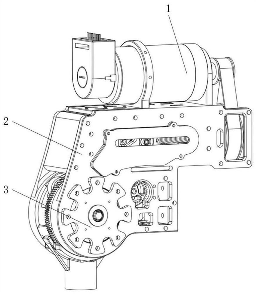
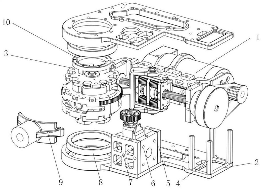
[0036] Such as figure 1 Shown: The patent of this invention is designed for the exoskeleton joints driven by variable damping and compliance, which is the most important part of the exoskeleton. The overall structure of variable damping compliant drive joint unit is as follows: figure 1 shown. It mainly includes three parts: a crank slider series elastic driver 1, an exoskeleton joint shell 2 and a magneto-rheological damper 3. exist figure 2 In the explosion diagram of the overall structure of the variable damping compliant drive joint, we can see the relationship between the various parts: the entire joint unit is based on the outer skeleton joint shell 2, with copper pillars 4, shell support plate 1-5, and shell support plate 26. Shell support plate 37 connects the upper and lower exoskeleton joint shells 2, and puts two joint rolling bearings 8 into ...


PUM


Abstract

The invention discloses a variable-damping flexibly-driven exoskeleton joint. The variable-damping flexibly-driven exoskeleton joint comprises a crank-slider series elastic driver, an exoskeleton joint shell and a magnetorheological damper, two joint rolling bearings are placed in the exoskeleton joint shell and used for supporting a joint center rotating body in the crank sliding block series connection elastic driver, other rod pieces or joints are connected through joint connecting pieces, and elastic elements are connected with the exoskeleton joint shell and the joint center rotating body respectively. A first magneto-rheological damper connecting block in the magneto-rheological damper is connected with an exoskeleton joint shell, a second magneto-rheological damper connecting block in the magneto-rheological damper is connected with a joint center rotating body, and the crank sliding block is connected with the elastic driver in series, and the magneto-rheological damper and the elastic element are connected in parallel. According to the invention, the mechanism can realize flexible driving and can resist external impact, so that the wearing comfort of the exoskeleton is improved.

Description

technical field [0001] The invention belongs to the technical field of mechanical joint units, in particular to an exoskeleton joint driven by variable damping and compliance. Background technique [0002] The joints of the exoskeleton mainly provide power for the wearer's joint movement. Most of the traditional exoskeleton joints use a scheme in which the motor and the reducer are connected in series and directly connected to the execution part, which makes the exoskeleton joint rigid and limits the wearer's flexibility and flexibility. Comfort; there is also a scheme of using series elastic actuators for driving, which can better reduce the impact of robot collisions, but the stiffness of series elastic actuators is fixed and cannot adapt to different working conditions, and the added elasticity The components will inevitably bring about vibration and low control accuracy. The existing solution to reduce the shortcomings of series elastic drives by adding damping cannot q...

Claims


Application Information

Patent Timeline
Patent Type & Authority Applications(China)
IPC IPC(8): B25J17/00B25J17/02B25J9/00B25J19/00
CPCB25J17/00B25J17/0208B25J9/006B25J19/0091
Inventor 朱爱斌邹佳峻宋纪元
Owner XI AN JIAOTONG UNIV
Why Eureka
Try Eureka