Supercharge Your Innovation With Domain-Expert AI Agents!

Gas turbine moving blade axial positioning structure and mounting and dismounting method

A gas turbine, axial positioning technology, applied in the direction of machines/engines, mechanical equipment, engine components, etc., can solve the problems of increasing the manufacturing cost and processing difficulty of the wheel disc, the large workload of disassembly and installation, and the high cost of manufacturing and maintenance. Achieve the effect of reducing installation and dismantling workload, reducing manufacturing and maintenance costs, and facilitating rotation

Pending Publication Date: 2022-03-22
DONGFANG TURBINE CO LTD
View PDF1 Cites 0 Cited by
  • Summary
  • Abstract
  • Description
  • Claims
  • Application Information

AI Technical Summary

Problems solved by technology

[0005] In the prior art, the dynamic and static air seals are arranged on the air inlet and outlet sides of the wheel, which makes the size of the wheel in the axial direction large, increasing the manufacturing cost and processing difficulty of the wheel
At the same time, the axial positioning structure is composed of multiple parts installed in a circumferential order, which requires a large amount of disassembly and installation work, and high manufacturing and maintenance costs

Method used


Image

  • Gas turbine moving blade axial positioning structure and mounting and dismounting method
  • Gas turbine moving blade axial positioning structure and mounting and dismounting method
  • Gas turbine moving blade axial positioning structure and mounting and dismounting method

Examples


Embodiment Construction

[0050] All features disclosed in this specification, or steps in all methods or processes disclosed, may be combined in any manner, except for mutually exclusive features and / or steps.

[0051] Any feature disclosed in this specification, unless specifically stated, can be replaced by other alternative features that are equivalent or have similar purposes. That is, unless expressly stated otherwise, each feature is one example only of a series of equivalent or similar features.

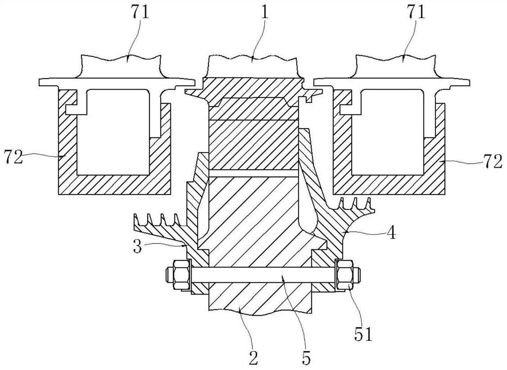
[0052] Such as figure 2As shown, the axial positioning structure of a gas turbine turbine blade in this embodiment includes a blade, a disc, a toothed air seal and a compression air seal;

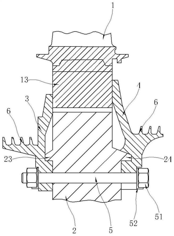
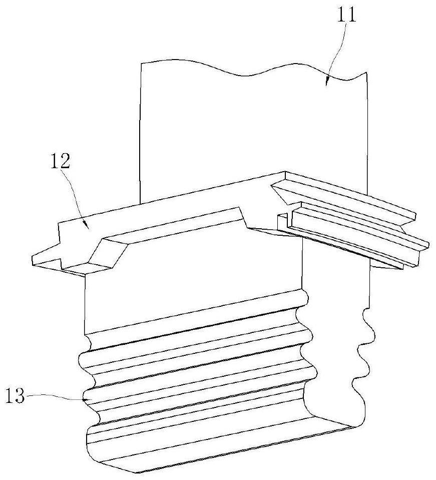
[0053] Such as image 3 As shown, the moving blade includes a blade shape, a blade root platform and a blade root, the blade root platform is arranged on the radial inner side of the blade shape, and the blade root is arranged on the radial inner side of the blade root platform; as Figure 4 As shown, the outer...


PUM


Abstract

The invention discloses a gas turbine moving blade axial positioning structure which comprises a moving blade, the moving blade comprises a blade profile, a blade root platform and a blade root, the blade root platform is arranged on the radial inner side of the blade profile, and the blade root is arranged on the radial inner side of the blade root platform; the wheel disc is provided with a blade root groove and a stud hole, and the blade root groove is matched and clamped with the blade root; the tooth-shaped air seal is concentric with the wheel disc and arranged on the air inlet side of the movable blade. The tooth-shaped air seal is provided with a kidney-shaped groove which faces the wheel disc and has a radian, and a first through hole matched with the stud hole is formed in the kidney-shaped groove. Peripheral teeth are arranged at the outer end part of the tooth-shaped air seal; the pressing air seal is concentric with the wheel disc and arranged on the air outlet side of the movable blade. The compression air seal is provided with a second through hole matched with the stud hole; the outer end part of the pressing air seal extends to the blade root groove; and the wheel disc, the tooth-shaped air seal and the compression air seal are fixed through studs and nuts. By adopting the axial positioning structure and the mounting and dismounting method for the turbine moving blade of the gas turbine, the manufacturing and maintenance cost can be reduced, and the mounting and dismounting workload of the moving blade can be reduced.

Description

technical field [0001] The invention relates to an axial positioning structure and an installation and disassembly method of a turbine blade of a gas turbine, belonging to the technical field of gas turbines. Background technique [0002] The turbine blade is axially installed in the blade root groove of the wheel disk through its blade root. The blade root forms of the turbine blade include T type, fir tree type and dovetail type, and the blade root groove in the wheel disk runs through the , in order to prevent the turbine blade from sliding in the blade root groove, the corresponding axial positioning structure of the turbine blade is required. [0003] Chinese patent application 201680052860.7 discloses a gas turbine device. The gas turbine device fixes the rotor blade axially on one side relative to the wheel through a locking plate. At the same time, the device further fixes the rotor blade relative to the wheel through another locking plate. Axially fixed on the othe...

Claims


Application Information

Patent Timeline
IPC IPC(8): F01D5/30F01D11/00
CPCF01D5/3007F01D11/003
Inventor 王刚德成露高进赵仕志陈晓平方宇赵世全艾松孔祥林田晓晶屈江吉黄涛齐雪冯国益
Owner DONGFANG TURBINE CO LTD
Features
  • R&D
  • Intellectual Property
  • Life Sciences
  • Materials
  • Tech Scout
  • Unparalleled Data Quality
  • Higher Quality Content
  • 60% Fewer Hallucinations
Learn More