
Multi-cavity regenerative combustion device suitable for non-premixed combustion

A combustion device, a premixed combustion technology, applied in the combustion type, burner, combustion method, etc., can solve the problems of difficult ignition, easy tempering, and insufficient combustion in a non-premixed combustion chamber, so as to improve the mixing efficiency and Effects of combustion efficiency, improved mixing, and low processing difficulty

Active Publication Date: 2022-03-22
HUAZHONG UNIV OF SCI & TECH
View PDF5 Cites 0 Cited by
  • Summary
  • Abstract
  • Description
  • Claims
  • Application Information

AI Technical Summary

Problems solved by technology

Although the premixed combustion oxidizer is better mixed with the fuel, and the combustion efficiency is higher, but it is prone to backfire during the combustion process, causing safety problems
In contrast, non-premixed combustion is the combustion of oxidant and fuel in the process of mixing, so there will be no flashback, but non-premixed combustion is prone to insufficient combustion, especially when the nominal equivalence ratio is close to 1.0 , and non-premixed combustion in a limited space is not easy to ignite, for example, the non-premixed combustion chamber in ZL201820127305.2 has the problem of difficult ignition

Method used


Image

  • Multi-cavity regenerative combustion device suitable for non-premixed combustion
  • Multi-cavity regenerative combustion device suitable for non-premixed combustion
  • Multi-cavity regenerative combustion device suitable for non-premixed combustion

Examples


Embodiment Construction

[0035] In order to make the object, technical solution and advantages of the present invention clearer, the present invention will be further described in detail below in conjunction with the accompanying drawings and embodiments. It should be understood that the specific embodiments described here are only used to explain the present invention, not to limit the present invention. In addition, the technical features involved in the various embodiments of the present invention described below can be combined with each other as long as they do not constitute a conflict with each other.

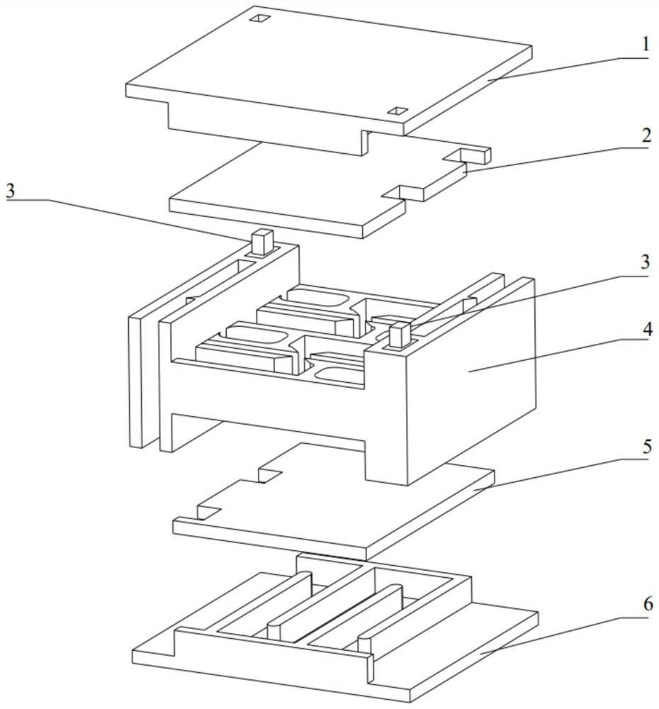
[0036] The invention provides a multi-chamber regenerative combustion device suitable for non-premixed combustion. The device utilizes the regenerative technology to reduce the heat loss of the exhaust gas and store a part of the heat through the heat storage structure to reduce the heat loss. , which improves the overall utilization of energy; the tapered structure is used in the fuel channel a...


PUM


Abstract

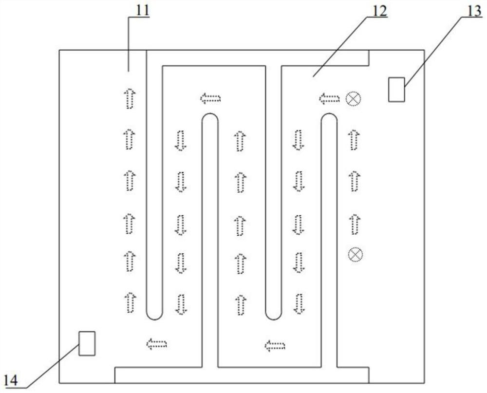
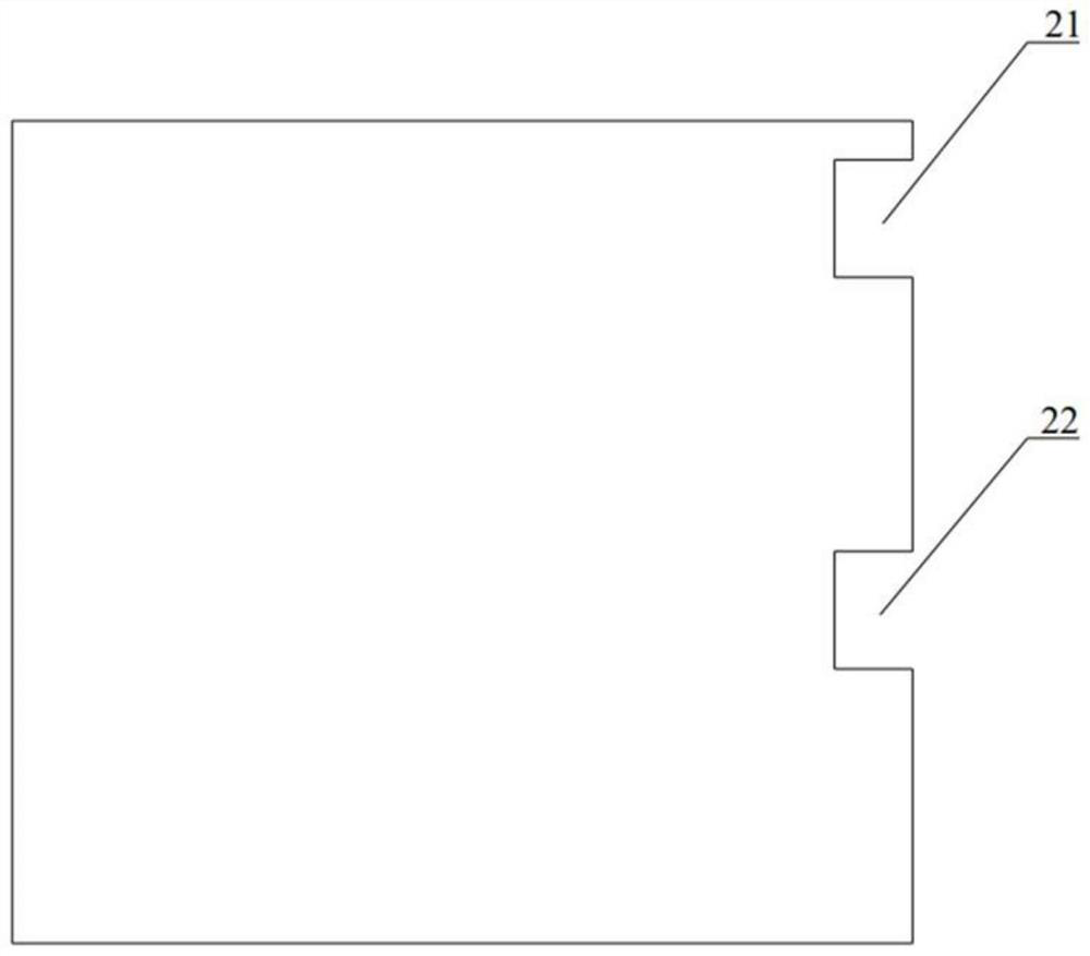
The invention belongs to the related technical field of gas diffusion combustion, and discloses a multi-cavity regenerative combustion device suitable for non-premixed combustion, which comprises a first regenerative channel shell, a body upper cover plate, a piezoelectric fire maker, a combustion chamber body, a body lower cover plate and a second regenerative channel shell, the first backheating channel shell, the body upper cover plate, the combustion chamber body, the body lower cover plate and the second backheating channel shell are sequentially connected, and the piezoelectric fire maker is arranged on the combustion chamber body; a first groove and a second groove are formed in the two opposite ends of the combustion chamber body correspondingly, and an oxidizing agent channel, a first igniter chamber, a fuel channel and a second igniter chamber are formed in the other two opposite ends of the combustion chamber body correspondingly. The two piezoelectric igniters are partially accommodated in the first igniter chamber and the second igniter chamber, respectively. The technical effects of being good in mixing effect, wide in combustible range, high in combustion efficiency, easy and convenient to ignite and high in applicability can be achieved.

Description

technical field [0001] The invention belongs to the technical field related to gas diffusion combustion, and more specifically relates to a multi-chamber regenerative combustion device suitable for non-premixed combustion. Background technique [0002] The rapid development of Micro-Electro-Mechanical Systems (MEMS) makes people's requirements for micro-power systems increase day by day. The currently widely used lithium-ion battery with the best effect has the disadvantages of short life, low energy density, and short validity period, and it will also cause potential pollution to the environment. In follow-up studies, it was found that the energy density of hydrocarbon fuels is dozens of times that of chemical batteries. Therefore, combustion-based micro-power generation systems, such as thermoelectric (TE) and thermophotovoltaic (TPV) devices, are considered as potential alternatives to the currently used portable chemical batteries. The micro-scale combustion chamber ca...

Claims


Application Information

Patent Timeline
Patent Type & Authority Applications(China)
IPC IPC(8): F23D14/20F23D14/46F23D14/58F23D14/62F23D14/66
CPCF23D14/20F23D14/46F23D14/58F23D14/62F23D14/66Y02E20/34
Inventor 范爱武李佳鑫王世轩
Owner HUAZHONG UNIV OF SCI & TECH
Learn More