Flue gas purification equipment for regenerative chamber of high-temperature rotary kiln

A flue gas purification and rotary kiln technology, applied in lighting and heating equipment, waste heat treatment, gas treatment, etc., can solve the problems of poor purification efficiency and achieve good purification efficiency

Pending Publication Date: 2022-03-22
JIANGXI BAOTAI NON FERROUS METAL GRP
View PDF7 Cites 0 Cited by
  • Summary
  • Abstract
  • Description
  • Claims
  • Application Information

AI Technical Summary

Problems solved by technology

[0005] In order to overcome the disadvantage of poor purification efficiency due to uneven purification of flue gas, the present invention provides a high-temperature rotary kiln regenerator flue gas purification equipment that can purify flue gas uniformly and has high purification efficiency

Method used


Image

  • Flue gas purification equipment for regenerative chamber of high-temperature rotary kiln
  • Flue gas purification equipment for regenerative chamber of high-temperature rotary kiln
  • Flue gas purification equipment for regenerative chamber of high-temperature rotary kiln

Examples


Embodiment 1

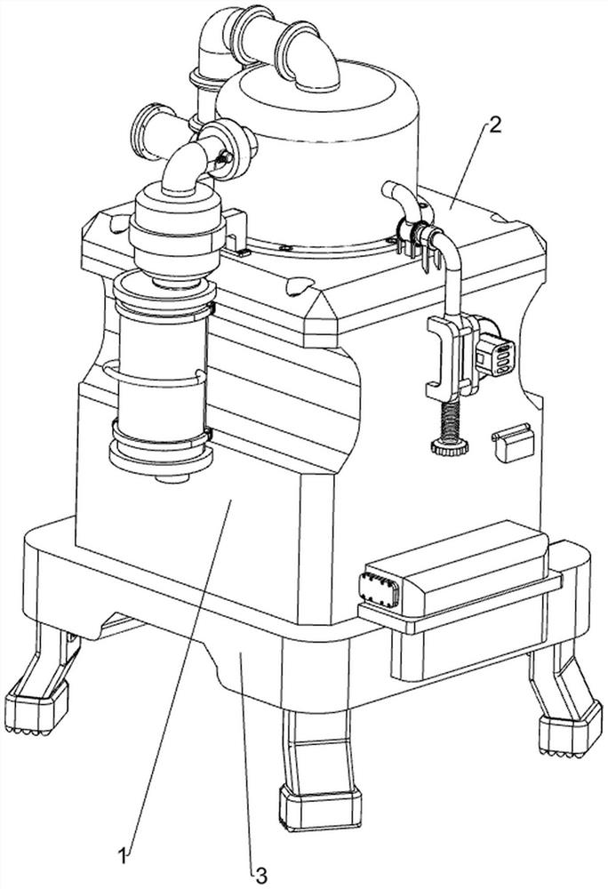
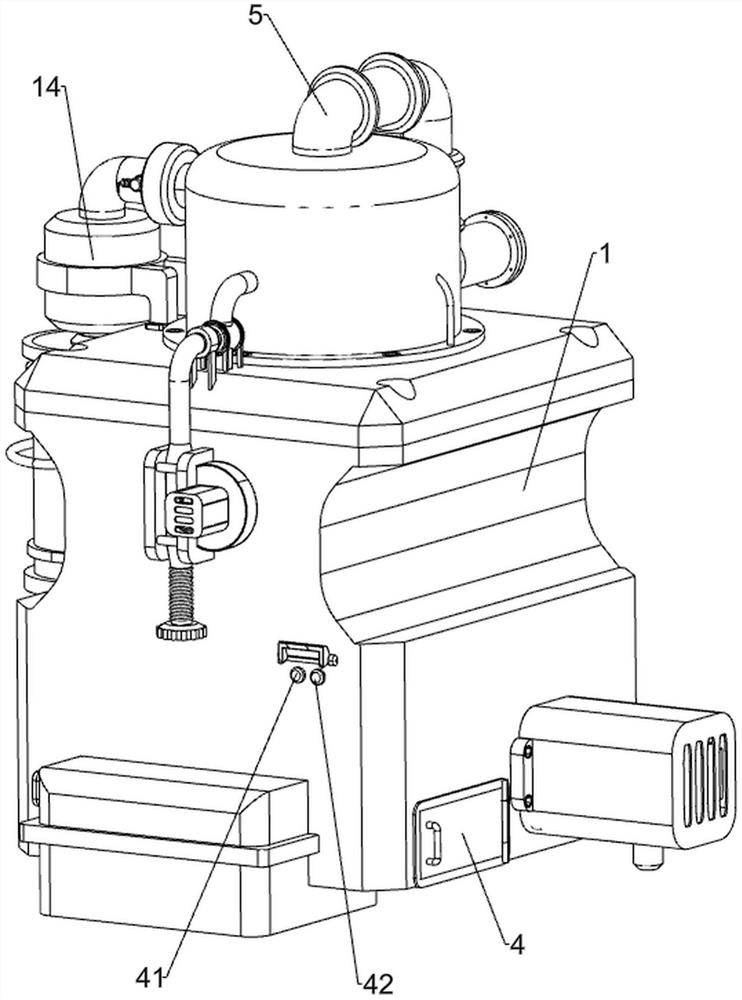
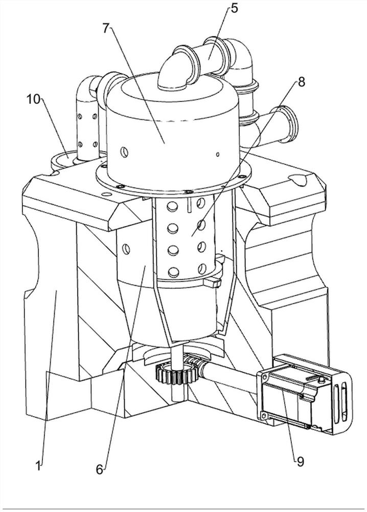
[0039] A high-temperature rotary kiln regenerator flue gas purification equipment, such as Figure 1-Figure 5 As shown, it includes installation base 1, sealing top plate 2, support bottom plate 3, start button 41, stop button 42, air intake pipe 5, sealing bottom cylinder 6, installation top cylinder 7, purification vertical cylinder 8, drive mechanism 9 and filter mechanism 10. The top of the installation base 1 is connected with the sealing top plate 2 by means of bolts, the bottom of the installation base 1 is fixedly connected with the support base plate 3, and the lower right part of the front side of the installation base 1 is fixed with the start button 41 and the stop button 42, the stop button 42 is located at the start On the right side of the button 41, the inner middle part of the installation base 1 is fixedly connected with the sealing bottom cylinder 6, and the upper part of the sealing bottom cylinder 6 is connected with the installation top cylinder 7 by means...

Embodiment 2

[0044] On the basis of Example 1, such as Figure 6-Figure 9 As shown, a scraper mechanism 11 is also included, and the scraper mechanism 11 includes a charging box 111, a discharge square tube 112, a perforated drum 113, a material removal stand 114, a limit wave plate 115, and a scraper brush plate 116, limit post 117, return guide rod 118 and return spring 119, the lower side of the front part of the installation base 1 is embedded with a charging box 111, the middle of the rear part of the charging box 111 is connected with a discharge square tube 112, and the vertical shaft 93 is fixed The upper part is fixed with a perforated drum 113, the discharge square tube 112 is set on the perforated drum 113, the discharge square tube 112 is connected with the perforated drum 113 in rotation, and the middle of the front side of the top of the perforated drum 113 passes through the bolt. The material removal stand 114 is connected in the same way, and the inner top wall of the puri...

Embodiment 3

[0049] On the basis of embodiment 1 and embodiment 2, such as Figure 6 , Figure 12 and Figure 13 As shown, a desulfurization mechanism 13 is also included, and the desulfurization mechanism 13 includes a water pump 131, a water flow sensor 132, a shunt pipe 133, a liquid storage tank 134, a spherical solenoid valve 135, a liquid level sensor 136, an atomizing nozzle 137 and The absorption sieve plate 138, the water pump 131 is fixedly connected to the upper middle part of the front side of the installation base 1, the diversion pipe 133 is connected to the middle part of the purification vertical cylinder 8, and the diversion pipe 133 is connected with the water pump 131, and the water flow is fixed in the middle of the top front side of the sealing top plate 2 The sensor 132 and the water flow sensor 132 can detect the water flow in the shunt pipe 133. A liquid storage barrel 134 is fixedly connected in the middle of the lower side of the rear part of the installation bas...


PUM


Abstract

The invention relates to purification equipment, in particular to flue gas purification equipment for a regenerative chamber of a high-temperature rotary kiln. The flue gas purification equipment for the regenerative chamber of the high-temperature rotary kiln, which can be used for uniformly purifying flue gas and is good in purification efficiency, needs to be designed. Flue gas purification equipment for a heat storage chamber of a high-temperature rotary kiln comprises a mounting base, a sealing top plate and a supporting bottom plate, the sealing top plate is fixedly connected to the top of the mounting base, and the supporting bottom plate is fixedly connected to the bottom of the mounting base. A servo motor is started to work, a fixed vertical shaft rotates to drive a buffer screw rod to rotate, the buffer screw rod enables flue gas to be uniformly discharged into a purification vertical cylinder, the purification vertical cylinder performs preliminary filtration on the flue gas, the flue gas is discharged into a filtering outer cylinder through a gas outlet pipe, a purification sieve plate performs deep sieving on the flue gas, and then the flue gas is discharged, so that the flue gas is discharged into the filtering outer cylinder. The flue gas can be uniformly purified, and the purification efficiency is good.

Description

technical field [0001] The invention relates to a purification device, in particular to a flue gas purification device for a regenerator of a high-temperature rotary kiln. Background technique [0002] As we all know, most of my country's industrial boilers and domestic boilers still use coal or oil as fuel. After burning, this fuel will produce a lot of dust and toxic gases, especially sulfur-containing gases, which will cause serious pollution to the surrounding environment. Most of them will purify the flue gas and then discharge it. [0003] Patent application CN109012074A, the publication date is 20181218. Disclosed is a combustion flue gas purification device, which includes a furnace and a flue gas inlet pipe, and is characterized in that: the furnace is provided with a smoke exhaust channel, the smoke exhaust channel is provided with a flue gas purifier, and the bottom of the flue gas purifier is provided with a There is a dust deposition box, the inside of the flue...

Claims


Application Information

Patent Timeline
Patent Type & Authority Applications(China)
IPC IPC(8): F27D17/00F27D19/00F27D25/00B01D46/10B01D46/24B01D46/681B01D53/14B01D53/18
CPCF27D17/008F27D19/00F27D25/001B01D46/10B01D46/2411B01D53/18B01D53/1475B01D2258/0283
Inventor 彭炳锋洪希西彭仁太
Owner JIANGXI BAOTAI NON FERROUS METAL GRP
Why Eureka
Try Eureka