Profile sound insulation structure based on particle damping and design method

A design method and particle technology, applied in the field of rail transit, can solve problems such as noise, achieve long life, good adaptability, and improve the effect of noise problems

Pending Publication Date: 2022-03-22
XIAMEN UNIV
View PDF0 Cites 0 Cited by
  • Summary
  • Abstract
  • Description
  • Claims
  • Application Information

AI Technical Summary

Problems solved by technology

[0004] The purpose of the present invention is to propose a profile sound insulation structure and design method based on particle damping, so as to improve the noise problem generated when high-speed railway trains run at high speed

Method used


Image

  • Profile sound insulation structure based on particle damping and design method
  • Profile sound insulation structure based on particle damping and design method
  • Profile sound insulation structure based on particle damping and design method

Examples


Embodiment 1

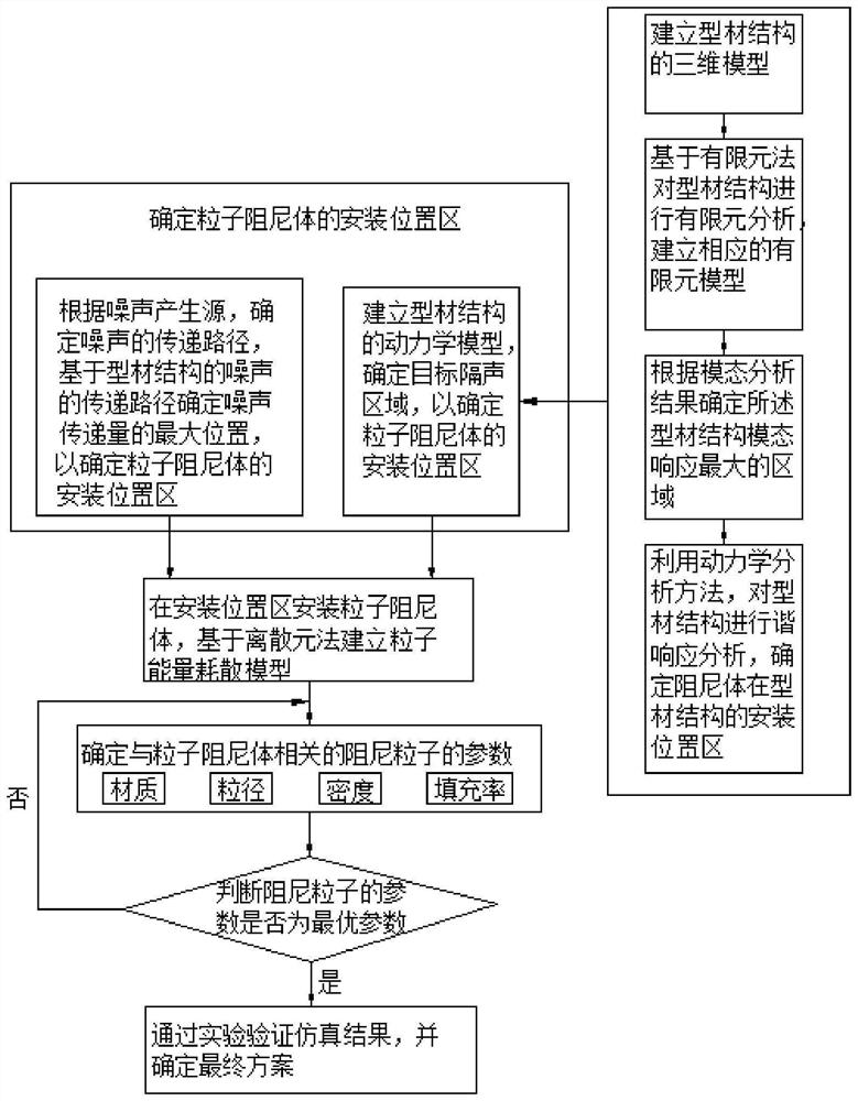
[0063] Such as figure 1 As shown, the design method of the profile sound insulation structure based on particle damping provided in this embodiment can be applied to the side wall, end wall, floor, roof (flat top or dome) of the high-speed rail train, etc., the present embodiment is based on Applying to the roof (flat roof) of high-speed rail trains as an example, the following steps are included:

[0064] S10: Determine the installation location area a of the particle damping body;

[0065] According to the noise generation source, determine the transmission path of the noise. The noise inside the car mainly comes from wheel-rail noise and aerodynamic noise, and the wheel-rail noise is transmitted into the car from the wheel set, floor, side wall, end wall, etc., and has little to do with the roof; a considerable part of the aerodynamic noise comes from the roof incoming. Determine the maximum position of the noise transmission amount based on the transmission path of the ...

Embodiment 2

[0091] Such as Figure 6-7 As shown, the difference between this embodiment and Embodiment 1 is:

[0092] The particle damping bodies inside the adjacent sound insulation units 15 are of the same type, and they are all the second particle dampers 3 .

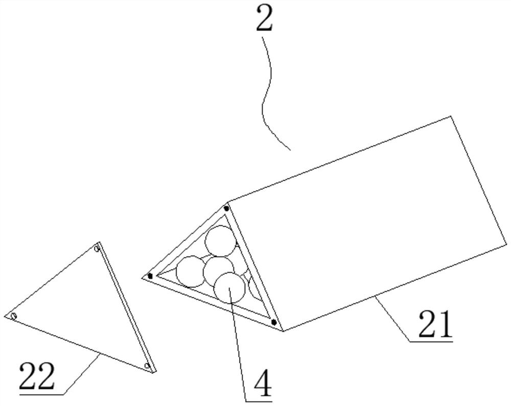
[0093] Wherein, the second particle damper 3 includes damping particles 4, a bag body 31, and a support body 32, the damping particle 4 is filled in the inner cavity 5 of the bag body 31, the support body 32 is arranged inside the sound insulation unit 15, and the bag body 31 After being supported by the support body 32, it is attached to the inner side wall of the sound insulation unit 15 to ensure that the bag body 31 is fully in contact with the inner surface of the sound insulation unit 15, thus ensuring a better sound insulation effect. In this embodiment, the outer side walls of the bag body 31 are attached to all side walls of the sound insulation unit 15 respectively.

[0094] In this embodiment, the thickness of the b...

Embodiment 3

[0096] Such as Figure 8 As shown, the difference between this embodiment and embodiment two is:

[0097] The outer wall of the bag body 31 is attached to the reinforcement.


PUM


Abstract

The invention discloses a profile sound insulation structure based on particle damping and a design method, and belongs to the field of rail transit, the design method of the profile sound insulation structure based on particle damping comprises the following steps: S10, determining a mounting position area of a particle damping body; s20, the particle damping body is installed in the installation position area of the particle damping body, and the energy consumption condition is counted based on a particle energy dissipation model established through a discrete element method to obtain the optimal vibration reduction effect; s30, parameters of damping particles related to the particle damping body are determined; and S40, verifying a simulation result through an experiment, and determining a final scheme. The sectional material sound insulation structure based on particle damping comprises a sectional material structure and a particle damping body, and the particle damping body is arranged in an installation position area of the sectional material structure. According to the profile sound insulation structure based on particle damping and the design method, the problem of noise generated when a high-speed railway train runs at a high speed is solved.

Description

technical field [0001] The invention belongs to the field of rail transit, and in particular relates to a particle damping-based profile sound insulation structure and a design method. Background technique [0002] Particle damping technology is a technology that provides damping by particles filled in the vibrating structure cavity (or additional cavity). When the structure vibrates, due to the kinematic coupling and energy transfer between the vibrating particle container and the internal particles, the particle Collision, friction, radiation noise, etc. are generated between the unit bodies and between the particle unit body and the vibration container, thereby dissipating the energy of the main vibration structure. [0003] With the rapid development of my country's economy, the construction speed of high-speed railway is getting faster and faster. High-speed railway trains have a series of characteristics such as fast running speed, large transportation capacity, low e...

Claims


Application Information

Patent Timeline
Patent Type & Authority Applications(China)
IPC IPC(8): G06F30/23B61D17/18G06F119/10G06F119/14
CPCG06F30/23B61D17/185G06F2119/14G06F2119/10
Inventor 肖望强邵堃
Owner XIAMEN UNIV
Why Eureka
Try Eureka