A welding process for h-shaped steel

A welding process, H-beam technology, applied in welding equipment, welding equipment, auxiliary welding equipment and other directions, can solve the problems of high labor intensity, low production efficiency, increased safety hazards, etc., to improve reset efficiency, compact structure, improve process safety effect

Active Publication Date: 2022-04-29
山东宏基石油机械设备有限公司
View PDF8 Cites 0 Cited by
  • Summary
  • Abstract
  • Description
  • Claims
  • Application Information

AI Technical Summary

Problems solved by technology

During the operation, it is necessary to manually wind the steel cable on the H-shaped steel, and then lift the H-shaped steel by lifting equipment, and turn it over by pulling the steel cable. Auxiliary operations are performed on the side, which has low production efficiency and high labor intensity, and also increases safety hazards

Method used


Image

  • A welding process for h-shaped steel
  • A welding process for h-shaped steel
  • A welding process for h-shaped steel

Examples


specific Embodiment approach

[0040] It should be noted that the structures, proportions, sizes, etc. shown in the drawings attached to this specification are only used to match the content disclosed in the specification, for those who are familiar with this technology to understand and read, and are not used to limit the implementation of the present invention Any modification of structure, change of proportional relationship or adjustment of size shall fall within the range covered by the technical content disclosed in the present invention without affecting the effect and purpose of the present invention. within range.

[0041] At the same time, terms such as "upper", "lower", "left", "right", "middle" and "one" quoted in this specification are only for the convenience of description and are not used to limit this specification. The practicable scope of the invention and the change or adjustment of its relative relationship shall also be regarded as the practicable scope of the present invention without...

Embodiment 1

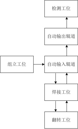
[0043] combined with figure 1 , present embodiment provides a kind of H-beam welding process, comprises the following steps:

[0044] Step S1, assembling: send one web and two wing plates to the assembling station, and perform automatic positioning, clamping, and spot welding through the automatic assembling equipment to complete the assembling of the H-beam;

[0045] Step S2, single-sided welding: put the assembled H-shaped steel horizontally into the automatic input roller table, enter the welding station through the automatic transmission roller table, and perform single-sided welding on the web and wing plates through automatic welding equipment;

[0046] Step S3, double-sided welding: the H-shaped steel welded on one side enters the turning station, and when all the H-shaped steel welded on one side enters the turning station, the turning equipment on the turning station lifts the H-shaped steel and turns it over 180° After that, it is re-sent to the welding station, and...

Embodiment 2

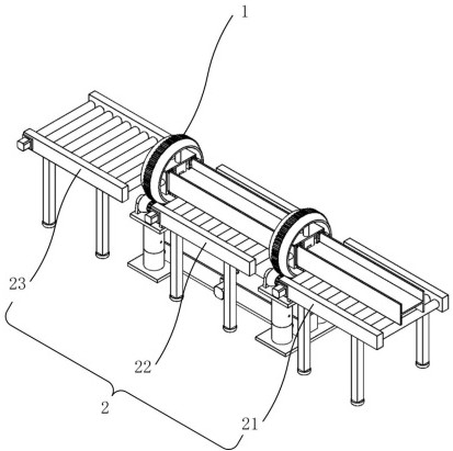
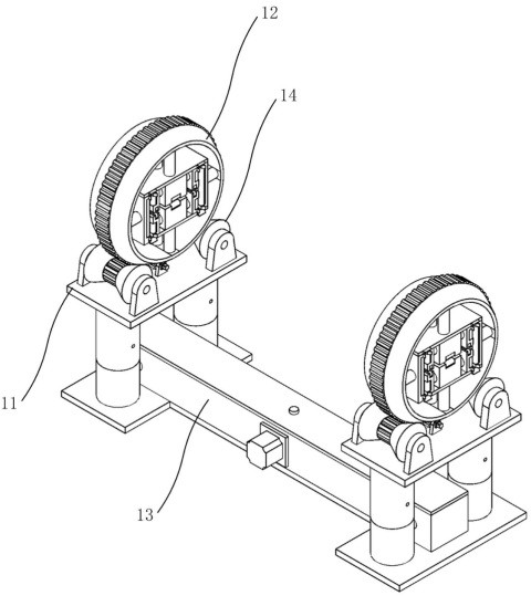
[0050] combined with figure 2 And attached image 3 , the present embodiment provides a turning device applicable to embodiment 1, the specific technical solution is as follows, the turning device includes a turning mechanism 1 and an automatic conveying roller set 2, and the turning mechanism 1 includes a set of rollers arranged at intervals along the conveying direction Two lifting platforms 11, the two lifting platforms 11 are respectively provided with clamping and rotating mechanisms 12, and the automatic conveying roller table set 2 includes a first roller table 21, a second roller table 22 and a third roller table 23, The first roller table 21 is arranged at one end of the turning mechanism 1 and docked with the automatic welding equipment. An infrared sensor (not shown in the figure) is arranged at the docking point, and the third roller table 23 is arranged at the turning point. At the other end of the mechanism 1 , the second roller table 22 is arranged between the...


PUM


Abstract

The present invention relates to the field of welding technology, in particular to a welding process for H-shaped steel, which includes the following steps: Step S1, assembly; The automatic transmission roller table enters the welding station for single-sided welding; step S3, double-sided welding: the H-beam after one-side welding enters the turning station, and when all the H-beams welded on one side enter the turning station, the turning work The flipping device on the station lifts the H-beam and flips it 180°, then sends it back to the welding station, and welds the other side; step S4, the H-beam after double-sided welding enters the automatic input roller table again, and is reversely conveyed To the automatic output roller table, output to the detection station through the output roller table. The process of the present invention has high safety, adopts the lifting type turning mechanism to realize the turning over of the H-shaped steel, has good process stability, saves energy consumption, and improves production efficiency.

Description

technical field [0001] The invention relates to the field of welding technology, in particular to an H-shaped steel welding process. Background technique [0002] H-shaped steel refers to a steel section with an H-shaped cross-section. It is welded by two parallel flanges and a web perpendicular to the flange. All parts of the H-shaped steel are arranged at right angles. Both have excellent bending resistance. Because H-shaped steel has many advantages such as light structure, simple construction, and cost saving, it has been widely used in various civil and industrial building structures. [0003] At present, the welding and forming process of H-shaped steel mainly includes the following process: first assemble the flange and web, and then transport the assembled H-shaped steel to the welding equipment through the roller table for unilateral welding. After the unilateral welding is completed, The H-beam is hoisted by lifting equipment, turned over with manual assistance, a...

Claims


Application Information

Patent Timeline
Patent Type & Authority Patents(China)
IPC IPC(8): B23K31/02B23K37/00B23K37/04B23K37/047
CPCB23K31/02B23K37/00B23K37/0443B23K37/047B23K2103/04
Inventor 高军李珊刘朝光
Owner 山东宏基石油机械设备有限公司
Why Eureka
Try Eureka