
Axial flow compression expansion type energy conversion device and control method

An energy conversion device, compression and expansion technology, which is applied to parts of pumping devices for elastic fluids, pump devices, axial flow pumps, etc., can solve the problem of low power level of the energy storage system, reduce energy loss, The effect of reducing radial offset and simple structure

Pending Publication Date: 2022-03-25
INST OF ENGINEERING THERMOPHYSICS - CHINESE ACAD OF SCI
View PDF6 Cites 0 Cited by
  • Summary
  • Abstract
  • Description
  • Claims
  • Application Information

AI Technical Summary

Problems solved by technology

[0004] Therefore, the technical problem to be solved by the present invention is to overcome the defect of low power level of the energy storage system in the prior art, so as to provide an axial flow compression expansion type energy conversion device and control method

Method used


Image

  • Axial flow compression expansion type energy conversion device and control method

Examples


Embodiment 1

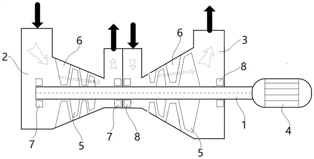
[0037] The axial-flow compression-expansion energy conversion device provided in this embodiment includes: a rotor shaft 1 , a compression cylinder 2 , an expansion cylinder 3 and a motor generator 4 .

[0038] Such as figure 1 As shown, the rotor shaft 1 has two sets of movable blades 5 arranged at intervals, and each group of multi-stage movable blades 5 includes two movable blades 5 arranged at intervals, and each movable blade 5 is vertically connected to the end of the rotor shaft 1 Zhou Xiang. The compression cylinder 2 has an inlet / exhaust port communicating with the outside world, and two-stage vanes 6 arranged at intervals on its inner wall; the expansion cylinder 3 has an inlet / exhaust port communicating with the outside world, and has intervals on its inner wall The two-stage static vane 6 that is set. Both the axial direction of the compression cylinder 2 and the expansion cylinder 3 have piercing holes, and the rotor shaft 1 penetrates into the interior of the c...

Embodiment 2

[0047] The control method for converting pressure energy and electric energy provided in this embodiment includes the following steps:

[0048] Pass low-pressure gas into the compression cylinder 2, after multi-stage compression, rise to high-pressure gas and discharge;

[0049] Pass high-pressure gas into the expansion cylinder 3, and after multi-stage expansion, it will be reduced to low-pressure gas and discharged;

[0050] When the compression power consumption of the compression cylinder 2 is greater than the expansion power production of the expansion cylinder 3, the motor generator 4 is switched to the output mode (as an electric motor) to provide power for the rotor shaft 1;

[0051] When the compression work of the compression cylinder 2 is less than the expansion work of the expansion cylinder 3, the motor generator 4 is switched to the input mode (as a generator), absorbing the mechanical energy of the rotor shaft 1 and converting it into electrical energy.


PUM


Abstract

The invention provides an axial flow compression expansion type energy conversion device and a control method. The axial flow compression expansion type energy conversion device is characterized in that a rotor shaft is provided with a plurality of groups of movable blades; the compression cylinder is arranged on the rotor shaft in a sleeving manner, and an air inlet / outlet communicated with the outside is formed in the compression cylinder; stationary blades are arranged on the inner wall of the compression cylinder, and the stationary blades and the movable blades in the compression cylinder are alternately arranged; the expansion cylinder is arranged on the rotor shaft in a sleeving manner, and an air inlet / outlet communicated with the outside is formed in the expansion cylinder; stationary blades are arranged on the inner wall of the expansion cylinder, and the stationary blades and the movable blades in the expansion cylinder are alternately arranged; and the motor generator is connected to the rotor shaft and is used for providing and absorbing mechanical energy. The axial flow compression expansion type energy conversion device can meet the requirements for large-flow and large-power energy conversion and storage, and is simple in structure.

Description

technical field [0001] The invention relates to the technical field of heat pump power storage, in particular to an axial flow compression expansion type energy conversion device and a control method. Background technique [0002] The energy storage system can improve the economy, security and stability of the power grid. It has been significantly developed in recent years. In order to further improve the efficiency of the compressed air energy storage system and the supercritical carbon dioxide energy storage The promotion effect of neutralization, large-scale and low-cost new energy storage technology urgently needs to be developed and put into operation. [0003] At present, the power levels of chemical and flywheel energy storage systems are generally small. High-power energy storage systems only have pumped water storage, compressed air energy storage, and supercritical carbon dioxide energy storage. However, the construction period of pumped storage systems is long and...

Claims


Application Information

Patent Timeline
Patent Type & Authority Applications(China)
IPC IPC(8): F04D19/00F04D25/04F04D25/06F01D15/08F01D15/10F01D1/04F04D25/16F04D29/66F01D13/02F01D3/02F04D29/58F01D25/08F04D29/38F04D29/54F01D5/14F01D9/02F04D29/056F01D25/16
CPCF04D19/00F04D25/045F04D25/06F01D15/08F01D15/10F01D1/04F04D25/163F04D29/662F01D13/02F01D3/02F04D29/5853F01D25/08F04D29/388F04D29/544F01D5/141F01D5/147F01D9/02F04D29/056F01D25/16F05D2300/611
Inventor 王亮张涵陈海生林曦鹏左志涛李文
Owner INST OF ENGINEERING THERMOPHYSICS - CHINESE ACAD OF SCI
Learn More