Novel non-deformation constant-air-leakage-rate sealing device for air pre-heater

A sealing device and air preheater technology, applied in the direction of heat exchanger shell, indirect carbon dioxide emission reduction, combustion method, etc., can solve the problems of losing the swing limit of the floating plate, hidden danger of operation, and high maintenance cost, and can eliminate the installation and welding process. , to ensure the flexibility of activities, to simplify the effect of the sealing structure

Pending Publication Date: 2022-03-25
华能(广东)能源开发有限公司海门电厂
View PDF0 Cites 0 Cited by
  • Summary
  • Abstract
  • Description
  • Claims
  • Application Information

AI Technical Summary

Problems solved by technology

It can be seen that the existing non-deformation and constant air leakage rate sealing device has many parts, complex structure, cumbersome installation, high precision requirements, and due to design problems, the structural welding position behind the limit device along the direction of rotation is limited, and the welding strength is insufficient. In the long-term start-stop process, the floating plate and the fan-shaped plate may be detached due to friction and impact, and the swing limit of the floating plate will be lost, which will cause potential safety hazards in operation, and the five limit devices corresponding to each floating plate are installed independently. Yes, it is difficult to adjust the coaxiality, and it is easy to be offset and displaced due to friction during use, resulting in jamming or even locking of the floating plate during operation, unable to achieve floating sealing, and the air leakage rate of the air preheater is greatly increased , when most of the floating plates lose the function of floating seal, the whole device will lose the function of constant sealing without deformation, and the air leakage rate is even higher than before the modification, which seriously affects the safety and economy of the whole boiler operation, and the maintenance cost is high. High difficulty

Method used


Image

  • Novel non-deformation constant-air-leakage-rate sealing device for air pre-heater
  • Novel non-deformation constant-air-leakage-rate sealing device for air pre-heater
  • Novel non-deformation constant-air-leakage-rate sealing device for air pre-heater

Examples


Embodiment 1

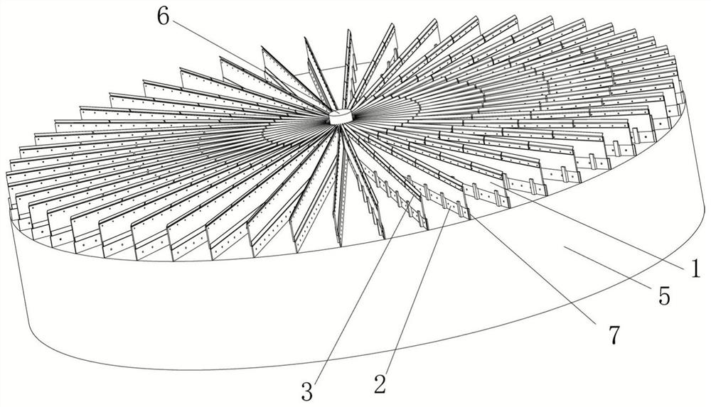
[0062] When installing, first place the limit plate 8 of the limit mechanism 2 on the rotor 5 and pre-attach it to the rear side of the storage grid plate 7 in the direction of rotation. Then, after aligning the fastening connection hole 16 of the limit plate 8 with the fastening hole 15 at the bottom of the compartment panel 7, use the fastener 24 to pass through the fastening connection. The hole 16 and the fastening hole 15 lock and fix the limiting plate 8 on the compartment grid plate 7, and the installation of the limiting mechanism 2 is completed.

[0063] After the installation of the limit mechanism 2 is completed, the rear end of the floating plate 1 is first placed in the limit groove 10 of the limit mechanism 2, and the horizontal section 13 of the limit support hook 9 arranged at five consecutive equal distances will float The plate 1 is stably supported and supported to facilitate the subsequent installation of the floating plate 1, and plays a role in the radial...

Embodiment 2

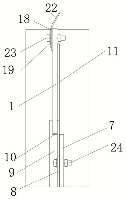
[0068] This embodiment is similar to Embodiment 1, the difference is that the vertical section 12 of the present embodiment is provided with a support reinforcement plate 14 outside, and the vertical section 12 is used to improve the position-limiting effect of the floating plate 1 through the support reinforcement plate 14, effectively extending the The service life of the limit mechanism 2 ensures long-term safe and stable operation of the non-deformable and constant air leakage rate sealing device of the present invention. The height of the limiting plate 8 of the present embodiment is 15 mm higher than the height of the compartment grid plate 7, and the floating plate 1 and the inner walls of the limiting groove 10 both sides have a movable gap of 1 mm, which can ensure the flexibility of the floating plate 1 while ensuring the limit. The position mechanism 2 has sufficient position swinging effect on the floating plate 1.

Embodiment 3

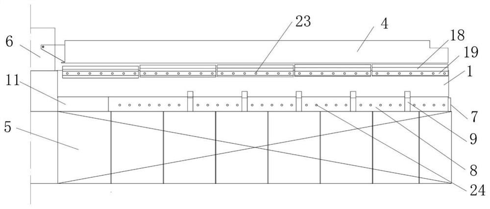
[0070] This embodiment is similar to Embodiment 1, the difference is that in this embodiment, according to the thermal deformation of the air preheater rotor 5, the distance between the upper end of the flexible sealing plate 18 and the lower end surface of the sector plate is sequentially set from back to front 13mm, 10mm, 6mm, 3mm, 2mm, after the rotor 5 is heated and bent downward, the gap distance between the top of the flexible sealing plate 18 and the bottom of the fan-shaped plate 4 remains stable, effectively improving the rotation balance of the rotor 5 during rotation, Reduce the occurrence of abnormal swing conditions.


PUM


Abstract

The invention discloses a novel non-deformation constant-air-leakage-rate sealing device of an air pre-heater. The flexible sealing device comprises a floating plate, a limiting mechanism and a flexible sealing mechanism, the flexible sealing mechanism is installed at the upper end of the floating plate through a connecting piece, the limiting mechanism is arranged between the floating plate and a bin grid plate and comprises a limiting plate and a limiting supporting hook, and the limiting supporting hook is arranged on the rear side of the limiting plate in the rotating direction; a limiting groove is formed between the limiting supporting hook and the sealing side of the limiting plate, the floating plate is placed in the limiting groove, and the front end face of the limiting plate is attached to the rear end face of a fixed reinforcing plate fixed to the center cylinder. The non-deformation constant air leakage rate device has the beneficial effects that compared with an existing non-deformation constant air leakage rate device, the structure is simple, installation is firm and reliable, and the problem that the existing non-deformation constant air leakage rate device is complex in assembly and disassembly procedures due to various structural parts is solved; and potential safety hazards caused by the fact that a limiting device is limited in welding position, poor in welding effect and prone to falling off after being collided, abraded and impacted by the sector plate are avoided, and disassembly, assembly and maintenance are convenient.

Description

technical field [0001] The invention relates to the technical field of sealing the hot end of an air preheater, and more particularly relates to a novel non-deformable and constant air leakage rate sealing device for an air preheater. Background technique [0002] The air preheater is a device that uses the heat of the flue gas discharged from the boiler to preheat the air required to enter the boiler for combustion, or as a recovery device for the heat of the boiler flue gas, so that the above heat can be used as fuel for dehumidification, heating and other purposes. The purpose of this equipment setup is to increase the efficiency of the boiler. [0003] The existing air preheater can be divided into tube box type and rotary type. The rotary air preheater is widely used in power plant boilers because of its large heat exchange area per unit volume and compact layout. However, the rotary air preheater The mushroom-like deformation of the rotor in the hot state will cause t...

Claims


Application Information

Patent Timeline
Patent Type & Authority Applications(China)
IPC IPC(8): F23L15/02F28F9/18
CPCF23L15/02F28F9/18Y02E20/34
Inventor 陈仲浩夏晓婷张家宽陈伟武纪洁鸿陈韶华史义明胡木林陈铁军蔡正春陈明光唐一多
Owner 华能(广东)能源开发有限公司海门电厂
Why Eureka
Try Eureka