Ultrasonic guided wave imaging method and system for anisotropic structure

An anisotropic, ultrasonic guided wave technology, applied in the analysis of solids using sonic/ultrasonic/infrasonic waves, material analysis using sonic/ultrasonic/infrasonic waves, and processing response signals of detection, etc. The problems of complex signals and poor imaging robustness can achieve the effect of accurate positioning imaging detection, avoiding the analytical solution process, and good robustness.

Active Publication Date: 2022-03-25
SOUTH CHINA UNIV OF TECH
View PDF3 Cites 1 Cited by
  • Summary
  • Abstract
  • Description
  • Claims
  • Application Information

AI Technical Summary

Problems solved by technology

However, the probabilistic imaging method has a better imaging effect in isotropic materials, but for anisotropic structures, the wave velocity changes with the direction, and it is impossible to obtain the corresponding elliptical path, so the elliptical probability imaging method is in the face of isotropic Good imaging effect cannot be obtained when the structure is heterosexual
On the other hand, the anisotropic structure and its inhomogeneity make the guided wave signal more complicated, and the weak nonlinear component causes its damage characteristics to fluctuate greatly, and the imaging robustness of partial sensing paths is poor

Method used


Image

  • Ultrasonic guided wave imaging method and system for anisotropic structure
  • Ultrasonic guided wave imaging method and system for anisotropic structure
  • Ultrasonic guided wave imaging method and system for anisotropic structure

Examples


Embodiment 1

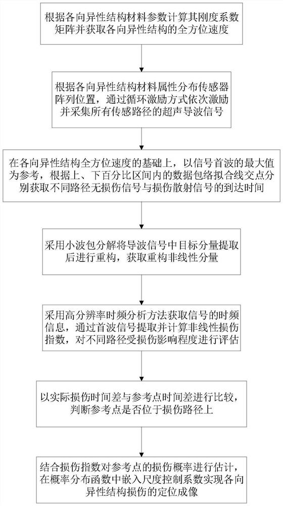
[0053] Such as figure 1 As shown, this embodiment provides an ultrasonic guided wave imaging method for anisotropic structures, including the following steps:

[0054] S1: Calculate the stiffness coefficient matrix according to the material parameters of the anisotropic structure and obtain the omni-directional velocity of the anisotropic structure;

[0055] In this embodiment, the omni-directional velocity of the anisotropic structure is obtained at one time by finite element simulation. In the simulation, the number of receiving sensors is N, and the number of receiving sensors is evenly distributed on a circle at the same distance from the exciting sensor as the center of the circle. According to the symmetry Receiving sensors can be reduced accordingly.

[0056] In this embodiment, the omni-directional velocity of the anisotropic structure is obtained by performing polynomial fitting on the guided wave velocity of each sensing path, and the degree of fitting polynomial is...

Embodiment 2

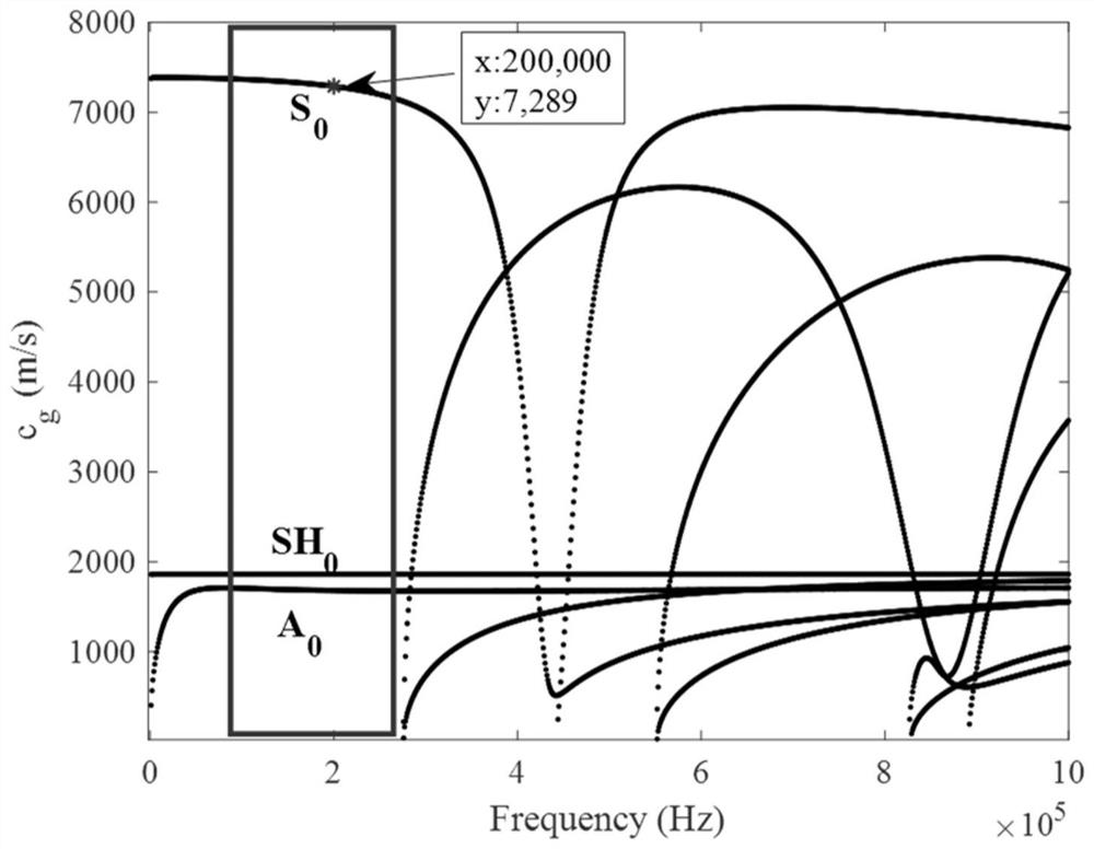
[0082] This embodiment selects the anisotropic CFRP structure with the ply direction [0 / 90 / 0] as a specific example based on the content of embodiment 1, and draws its dispersion curve according to the material parameters, such as figure 2 As shown, according to the dispersion curve, the excitation frequency is determined to be 200kHz. At this time, there are fewer guided wave modes and the speed is relatively stable.

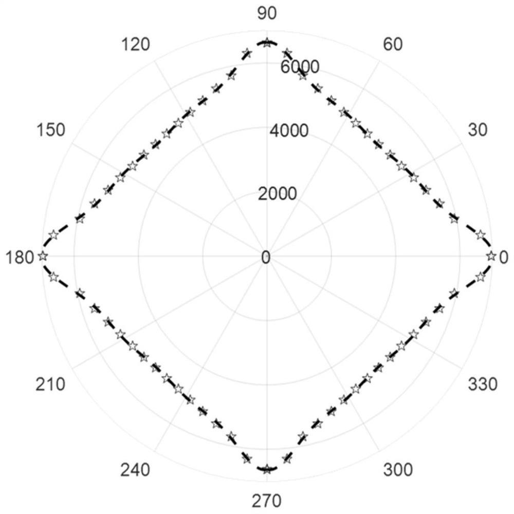
[0083] In this embodiment, an anisotropic CFRP structure simulation model is established, and 17 receiving sensors are evenly distributed on a circle 200 mm away from the exciting sensor with the exciting sensor as the center of the circle, and the guided wave velocities at different angles are obtained by using the threshold method. Such as image 3 As shown, the omni-directional velocity of the anisotropic CFRP structure is obtained by an 8th degree polynomial fitting.

[0084] In this embodiment, a circular array layout is adopted, and all sensors are cycl...

Embodiment 3

[0107] This embodiment provides an ultrasonic guided wave imaging system for anisotropic structures, including: a stiffness coefficient matrix calculation module, an omni-directional velocity acquisition module, an ultrasonic guided wave signal acquisition module, a signal arrival time acquisition module, and nonlinear component reconstruction Module, time-frequency information analysis module, nonlinear damage index acquisition module, damage path determination module, damage location imaging module;

[0108] In this embodiment, the stiffness coefficient matrix calculation module is used to calculate the stiffness coefficient matrix according to the anisotropic structural material parameters;

[0109] In this embodiment, the omnidirectional velocity acquisition module is used to acquire the omnidirectional velocity of the anisotropic structure;

[0110] In this embodiment, the ultrasonic guided wave signal acquisition module is used to distribute the position of the sensor ar...


PUM


Abstract

The invention discloses an ultrasonic guided-wave imaging method and system for an anisotropic structure, and the method comprises the steps: calculating a stiffness coefficient matrix according to the material parameters of the anisotropic structure, obtaining an omnibearing speed, and sequentially exciting and collecting the ultrasonic guided-wave signals of all sensing paths; according to data envelope fitting line intersection points in the upper percentage interval and the lower percentage interval, obtaining arrival time of non-damage signals and damage scattering signals in different paths; extracting a target component in the guided wave signal to obtain a reconstructed nonlinear component, obtaining time-frequency information of the signal, extracting and calculating a nonlinear damage index through a head wave signal, and evaluating the damage influence degree of different paths; and comparing the actual damage time difference with the reference point time difference, determining a damage path, estimating the damage probability of the reference point by combining the damage index, and embedding a scale control coefficient in a probability distribution function to realize the positioning imaging of the anisotropic structure damage. According to the method, high-precision accurate positioning imaging is realized, and the robustness is high.

Description

technical field [0001] The invention relates to the technical field of nondestructive testing and structural health monitoring, in particular to an ultrasonic guided wave imaging method and system for anisotropic structures. Background technique [0002] Advanced composite structures are highly valued in the fields of aviation and marine high-end equipment due to their excellent comprehensive performance, but the anisotropy and other characteristics of composite structures also bring difficulties to their structural health monitoring and damage detection. [0003] Due to the difference in properties between different materials, defects such as delamination and cracks are easily formed inside the anisotropic composite structure, especially at the interface between different components, during manufacturing and use. In addition, the service environment of anisotropic structures in the field of aerospace and marine high-end equipment is very harsh, which will undoubtedly increa...

Claims


Application Information

Patent Timeline
Patent Type & Authority Applications(China)
IPC IPC(8): G01N29/06G01N29/44
CPCG01N29/069G01N29/4472
Inventor 洪晓斌刘远李彬彬
Owner SOUTH CHINA UNIV OF TECH
Why Eureka
Try Eureka