Method for improving isolation degree of continuous wave SAR (Synthetic Aperture Radar) by utilizing azimuth difference

A technology of azimuth difference and isolation, applied in the field of microwave remote sensing, can solve the problems of insufficient working distance and long working distance of spaceborne SAR applications, and achieve the effect of low cost, simple structure and strong penetrability

Pending Publication Date: 2022-03-25
AEROSPACE DONGFANGHONG SATELLITE
View PDF0 Cites 0 Cited by
  • Summary
  • Abstract
  • Description
  • Claims
  • Application Information

AI Technical Summary

Problems solved by technology

[0005] The problem solved by the technology of the present invention is: aiming at the problem that the existing continuous wave SAR system is limited by the isolation degree of transmission and reception, the problem of insufficient action distance and the characteristics of the long action distance of spaceborne SAR app

Method used


Image

  • Method for improving isolation degree of continuous wave SAR (Synthetic Aperture Radar) by utilizing azimuth difference
  • Method for improving isolation degree of continuous wave SAR (Synthetic Aperture Radar) by utilizing azimuth difference
  • Method for improving isolation degree of continuous wave SAR (Synthetic Aperture Radar) by utilizing azimuth difference

Examples


Example Embodiment

[0057] Example:

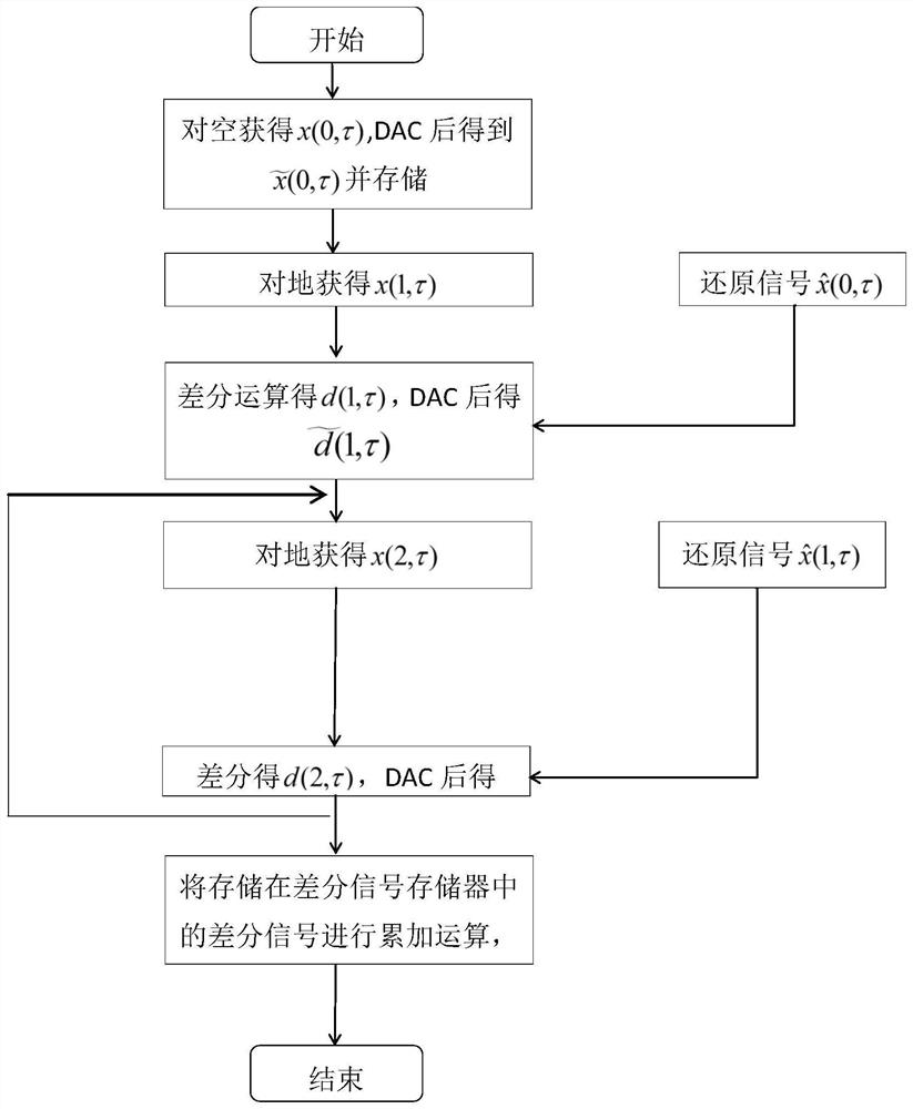
[0058] The specific steps of a method for improving CW SAR isolation by using azimuth difference provided in a specific embodiment of the present invention are as follows:

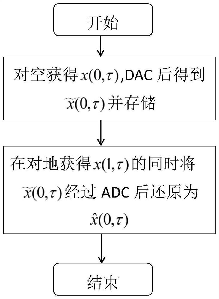
[0059] (1) First, the SAR irradiates the air to obtain the initial input RF signal x(0, ​​τ), and performs AD transformation to obtain a discrete digital signal and stored in the signal memory, The signal consists only of leakage signals;

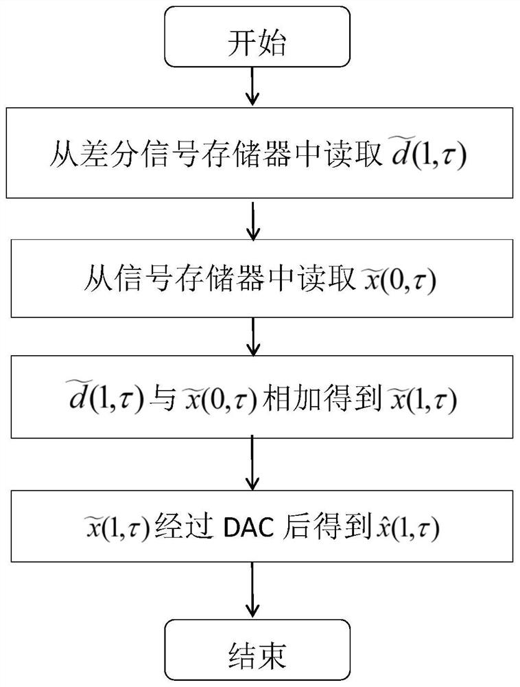
[0060] (2) The first radio frequency signal x(1, τ) is obtained by irradiating the SAR to the ground, and the signal is composed of the leakage signal and the echo signal. At the same time, the data stored in the signal memory will be The signal is subjected to DA transformation to obtain the restored signal of x(0,τ) After differential processing, a differential signal dominated by the echo signal is obtained The differential signal d(1,τ) is AD transformed to get Stored in the differential signal memory;

[0061] The present invention ad...

Example Embodiment

[0075] Simulation example:

[0076] After the simulation test of the present invention, in order to verify the above-mentioned inventive method, the present invention simulates the method for improving the isolation degree of the continuous wave SAR by the azimuth difference. The main simulation settings are as follows:

[0077] 1. System parameters:

[0078] Transmitting power: 4800W

[0079] Radar range: 800Km;

[0080] Echo received power: -109dBm

[0081] Leakage signal power: -1dBm

[0082] Quantization bits: 8bit

[0083] Bandwidth: 48MHz

[0084] Pulse width: 20us

[0085] Sampling rate: 96MHz

[0086] FM slope: 2.4051e12

[0087] Slope distance from the center of the scene: 800km

[0088] Simulation results:

[0089] The simulation results are shown in Figure 4(a), Figure 4(b), Figure 5(a), Figure 5(b), Image 6 As shown, the leakage signal received in the simulation is 110dB higher than the echo signal power. Figure 4(a) and Figure 4(b) a...


PUM


Abstract

The invention relates to a method for improving the isolation degree of a continuous wave SAR (Synthetic Aperture Radar) by utilizing azimuth difference, the continuous wave SAR has the characteristics of low peak power, high system efficiency, small size and the like and is a direction of SAR development at present, the suppression of a leakage signal is a key difficulty of the continuous wave SAR, and according to the characteristic of slow change of the leakage signal in the azimuth, the isolation degree of the continuous wave SAR is improved. According to the method, the leakage signal is suppressed by using the azimuth difference, and then the transceiving isolation is improved, and theoretical and simulation results show that the method can realize signal separation under the condition that the leakage signal is 110dB larger than an echo signal, and can lay a foundation for the application of the continuous wave SAR on a satellite platform.

Description

technical field [0001] The invention relates to a method for improving the isolation degree of continuous wave SAR by utilizing azimuth difference, and belongs to the field of microwave remote sensing. Background technique [0002] Compared with the conventional pulsed SAR system, the continuous wave SAR system has the characteristics of small size, light weight, low cost and low peak transmit power. At present, continuous wave SAR has many applications in the field of early warning and monitoring. For spaceborne SAR applications, continuous wave SAR also has certain advantages. The spaceborne radar has a long range, and continuous wave SAR can reduce the peak transmit power and adapt to satellites. The development needs of platform miniaturization, light weight and low power consumption. However, the continuous wave SAR transceiver channels work at the same time, and improving the isolation of the transceiver channels is a key problem to be solved. [0003] Due to the exi...

Claims


Application Information

Patent Timeline
IPC IPC(8): G01S13/90G01S7/41
CPCG01S13/90G01S7/41
Inventor 冯锦焦军军范志芳梅名宣范宇杰武泓涵吕鹏
Owner AEROSPACE DONGFANGHONG SATELLITE
Why Eureka
Try Eureka