
Linear magnet power supply based on H bridge

A magnet and power supply technology, applied to electrical components, output power conversion devices, AC power input conversion to DC power output, etc., to achieve the effects of superior output current resolution, fast response, and reduced output current ripple

Pending Publication Date: 2022-03-25
UNIV OF SCI & TECH OF CHINA
View PDF0 Cites 0 Cited by
  • Summary
  • Abstract
  • Description
  • Claims
  • Application Information

AI Technical Summary

Problems solved by technology

[0003] The technical problem of the present invention is to overcome the deficiencies of the prior art, starting from the requirement of correcting the magnet power supply, and combining the advantages of the H-bridge topology and the linear power supply, a design scheme of a linear magnet power supply based on the H-bridge is proposed, which effectively takes into account the correction To meet the requirements of rapidity and stability of the magnet power supply, the invention utilizes the characteristics of the H-bridge structure that can realize bipolar current output, combines the low ripple noise characteristics of the power device in the linear working area, and the power supply system has no high-frequency switching noise, While realizing the bidirectional switching requirements of the magnet load on the output current, it effectively takes into account the magnet load current requirements of high stability and low ripple

Method used


Image

  • Linear magnet power supply based on H bridge
  • Linear magnet power supply based on H bridge
  • Linear magnet power supply based on H bridge

Examples


Embodiment Construction

[0019] The present invention will be described in detail below in conjunction with the accompanying drawings and embodiments.

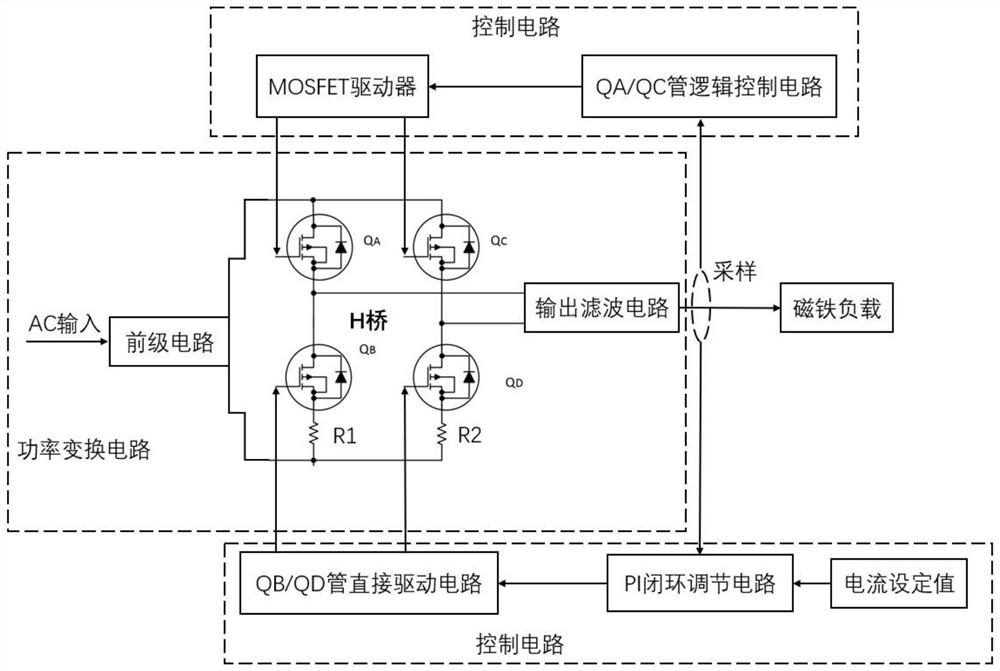
[0020] Such as figure 1 As shown, an H-bridge-based linear magnet power supply of the present invention includes: a power conversion unit and a control unit. The power conversion unit includes an AC input connected in sequence, a pre-stage circuit, an H-bridge composed of four switching devices QA, QB, QC and QD (not shown in the figure), and an output filter circuit, which is used to convert the AC power of the external power grid to The signal is converted into a DC signal required by the magnet load; one end of the control unit is connected to the output filter circuit in the power conversion unit for sampling the DC signal, and the other end is connected to the H bridge in the power conversion unit , used to drive and control the H-bridge, and then adjust the DC signal.

[0021] The grid alternating current signal input by AC is rectified and st...


PUM


Abstract

The invention discloses a linear magnet power supply realized based on an H-bridge circuit, which consists of a power conversion circuit and a control circuit, and is characterized in that a core H bridge in the power conversion circuit is provided with four bridge arms; the upper bridge arm is used for switching the polarity of output current, and the lower bridge arm always works in a linear amplification region and provides current output for a magnet load. And a current set value is given by the high-precision digital-to-analog converter module, so that high precision and high resolution of power output are ensured. The working voltage of the lower bridge arm of the H bridge is adjusted through the peripheral control circuit, so that the lower bridge arm works in a linear region and is equivalent to a variable resistor, and the output current is adjusted through real-time closed-loop feedback of the peripheral control circuit. The characteristic that bipolar current output is achieved through an H-bridge structure is utilized, the characteristic of low ripple noise of a power device in a linear working area is combined, a power system is free of high-frequency switching noise, and the requirement for high-stability and low-ripple magnet load current is effectively considered while the requirement for bidirectional switching of output current of a magnet load is met.

Description

technical field [0001] The invention relates to a linear magnet power supply based on an H bridge. Specifically, the upper half bridge arm of the H bridge is used to switch the current polarity, and the switching device of the lower half bridge arm works in the linear amplification area to realize the adjustment of the magnet load current. a method of Background technique [0002] In the electron storage ring, the correction magnet power supply is an important component for real-time correction of the beam position. Because it requires fast response speed and high stability at the same time, it brings challenges to researchers. The switching power supply has the advantage of high efficiency, but because the power device needs to work in a high-frequency switching state, it will bring ripple noise interference to the system. The key parameters for a rectified magnet power supply are response speed and low output current ripple, while the power level is low so that it can be...

Claims


Application Information

Patent Timeline
Patent Type & Authority Applications(China)
IPC IPC(8): H02M7/219H02M1/088H02M1/14H02M1/44
CPCH02M7/219H02M1/088H02M1/14H02M1/44
Inventor 邵琢瑕高辉张海燕胡保进
Owner UNIV OF SCI & TECH OF CHINA
Learn More