
Manufacturing method of composite sabot of armor-piercing bullet and sabot

A manufacturing method and technology of armor-piercing projectiles, which are applied in the directions of warheads, ammunition, weapon accessories, etc., can solve the problems of fully exerting fiber ability and high negative quality in the way of laying, and achieve light weight, high export speed, and high performance utilization. Effect

Pending Publication Date: 2022-03-29
XIAN YINGLIKE ELECTRIC TECH CO LTD
View PDF0 Cites 2 Cited by
  • Summary
  • Abstract
  • Description
  • Claims
  • Application Information

AI Technical Summary

Problems solved by technology

Although the existing technology uses high-strength carbon fiber cloth as a reinforcing material, its laying method and material selection cannot fully exert the ability of all fibers, and theoretically speaking, the negative quality is still high

Method used


Image

  • Manufacturing method of composite sabot of armor-piercing bullet and sabot
  • Manufacturing method of composite sabot of armor-piercing bullet and sabot
  • Manufacturing method of composite sabot of armor-piercing bullet and sabot

Examples


Embodiment 1

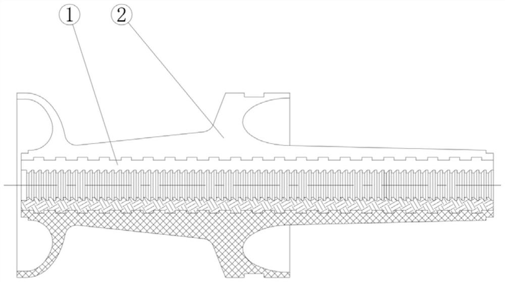
[0034] A method for manufacturing a composite armor-piercing projectile support flap, which mainly includes four parts: support core production, external side saddle injection molding, cutting and mechanical processing. The production of the support core uses a carbon fiber prefabricated body as the reinforcing material at the joint with the penetrating rod, and the high-strength support core 1 with internal teeth is produced through the RTM process. The specific method is: first, according to the outer contour of the penetrating body and the supporting surface The braided mandrel is made of graphite, and then a three-dimensional circular weaving preform of high-strength carbon fiber filaments is used on the graphite mandrel. During circular weaving, the inner warp yarn is pressed into the tooth groove of the graphite mandrel under the action of the tension of the weft yarn in the circular direction. Form a tight incarceration; before dipping, put support rings outside the pref...

Embodiment 2

[0036] A method for manufacturing a composite armor-piercing projectile support flap, which mainly includes four parts: support core production, outer saddle molding, cutting and mechanical processing. The production of the support core uses the PBO fiber prefabricated body as the reinforcing material at the joint with the penetrating rod, and the high-strength support core with internal teeth is produced through the RTM process. The specific method is: first, according to the outer contour of the penetrating body and the supporting surface Use graphite to make the braiding mandrel, and then use PBO fiber filament three-dimensional circular weaving prefabricated body on the graphite mandrel. Specifically, it adopts a heavy backward structure with axial yarns. The warp yarn is pressed into the tooth groove of the graphite core shaft to form a tight incarceration, and the heavy back structure can significantly improve the single-directional effect of the warp yarn, making the sup...


PUM


Abstract

The manufacturing method comprises the following steps that a high-strength fiber prefabricated body is adopted as a reinforcing material at the joint of the high-strength fiber prefabricated body and a penetration rod, and a support core with inner teeth is manufactured through an RTM technology; performing external molding on the support core by adopting injection molding or mold pressing to form a preparation part; cutting the prepared part to form a plurality of supporting petals; the supporting petals are placed on the steel mandrel which is the same as the matching surface of an actual penetration body and fastened through the rope, then the supporting petals are turned to the specified size, the fastening rope on the supporting petals is unfastened, and manufacturing is completed. The performance utilization rate of the reinforced fibers in the composite material is high, the weight of the sabot is lighter, and the outlet speed of a penetration body is higher under the condition of the same explosive loading amount.

Description

technical field [0001] The invention belongs to the technical field of three-dimensional braided bullet holders, and in particular relates to a method for manufacturing a composite bullet holder for armor-piercing bullets and the bullet holder. Background technique [0002] The shell of the armor-piercing projectile is usually composed of 3 to 4 saddle-shaped petals evenly distributed. The ring or helical teeth on the inner side of the shell are meshed with the teeth penetrating the outer circle and act on the shell when the gun is fired. The force is transmitted to the penetrating body so that the penetrating body and the bullet holder move at high speed together; the front chamber of the front centering part of the bullet holder flap will generate a radial separation force after flying out of the muzzle to separate the bullet holder from the penetrating body; The bullet belt that is made of soft material can play a sealing role in the gun bore to prevent high-pressure gas ...

Claims


Application Information

Patent Timeline
Patent Type & Authority Applications(China)
IPC IPC(8): B29C45/00B29C43/18B29C43/32B29C45/14B29C70/48F42B12/04F42B14/06
CPCB29C70/48B29C45/14B29C45/0055B29C43/18B29C43/32F42B14/068F42B14/06F42B12/04
Inventor 吉少波李杰李凤珍朱军胡国斌李凤芝
Owner XIAN YINGLIKE ELECTRIC TECH CO LTD
Learn More