
Lens assembly, lens module, laser module and laser radar device

A lens component and lens technology, applied in the laser field, can solve the problems of high defect rate and poor consistency of laser modules, and achieve the effect of avoiding direct contact and avoiding fragmentation

Active Publication Date: 2022-03-29
湖南阿秒光学科技有限公司
View PDF5 Cites 3 Cited by
  • Summary
  • Abstract
  • Description
  • Claims
  • Application Information

AI Technical Summary

Problems solved by technology

[0003] In order to overcome the deficiencies of the prior art, embodiments of the present invention provide lens components, lens modules, laser modules and laser radar devices to solve the problems of high defect rate and poor consistency of laser modules in the prior art

Method used


Image

  • Lens assembly, lens module, laser module and laser radar device
  • Lens assembly, lens module, laser module and laser radar device
  • Lens assembly, lens module, laser module and laser radar device

Examples


Embodiment Construction

[0060] The following will clearly and completely describe the technical solutions in the embodiments of the present invention with reference to the accompanying drawings in the embodiments of the present invention. Obviously, the described embodiments are only part of the embodiments of the present invention, not all of them. Based on the embodiments of the present invention, all other embodiments obtained by persons of ordinary skill in the art without creative efforts fall within the protection scope of the present invention.

[0061] It should be noted that if there is a directional indication (such as up, down, left, right, front, back...) in the embodiment of the present invention, the directional indication is only used to explain the relationship between the components in a certain posture. If the specific posture changes, the directional indication will also change accordingly.

[0062] In addition, if there are descriptions involving "first", "second" and so on in the...


PUM


Abstract

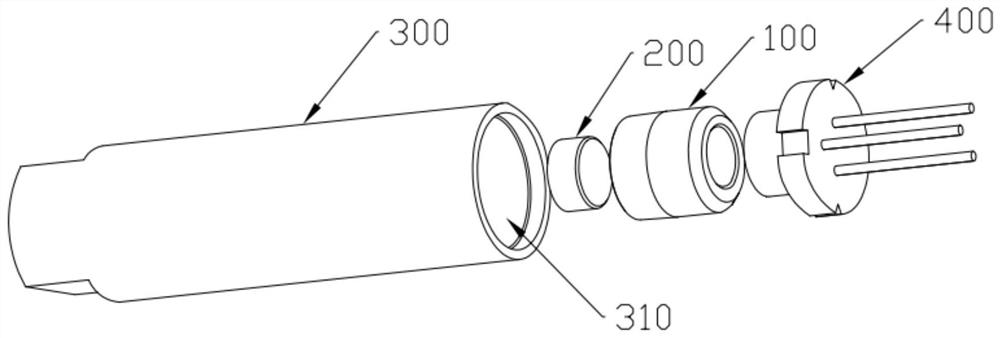
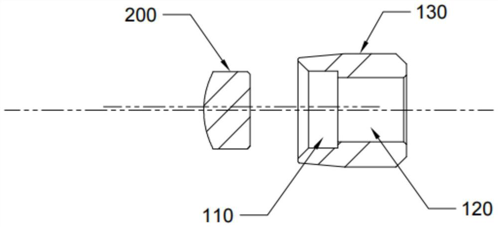
The invention provides a lens assembly, a lens module, a laser module and a laser radar device. The lens assembly comprises a lens fixing seat and a lens. The lens fixing seat is provided with an accommodating hole. And the lens is arranged in the accommodating hole of the lens fixing seat. The optical axis of the lens and the central symmetry axis of the outer wall face of the lens fixing base are parallel to each other and spaced by a preset distance. According to the invention, the central symmetry axis of the lens fixing seat and the central symmetry axis of the lens are parallel to each other and are spaced by the preset distance, so that when the lens assembly is applied to the laser radar device of the sweeping robot, the light emitted by the laser assembly can be deflected by a certain angle, and the actual application requirement of the laser radar device is met.

Description

technical field [0001] The invention belongs to the field of laser technology, and in particular relates to a lens assembly, a lens module, a laser module and a laser radar device. Background technique [0002] In 2009, Neato released a laser radar for robots. The laser radar uses the triangular ranging method between the laser transmitter and receiver to measure the distance to obstacles. The laser ranging sensor is installed on the motor. , measure the distance within a 360° circle by rotating, and draw an indoor map based on this. The laser transmitter is one of the core components of lidar. In conventional application scenarios, in order to adjust the focal length of the laser emitter, and then adjust the position and shape of the projection spot generated by the laser emitter to meet the standard, the laser emitter is usually set in a two-stage structure. The optical lens is located in one section, and the laser assembly is located in the other section. The two-sectio...

Claims


Application Information

Patent Timeline
IPC IPC(8): G01S7/481
CPCG01S7/481
Inventor 黄柏良
Owner 湖南阿秒光学科技有限公司
Learn More