Powdered scrap removing device for plate cutting

A technology for removing device and dust, applied in bark area/debris/dust/waste removal, wood processing equipment, stone processing equipment, etc. Reduce the effect of bristle deformation

Active Publication Date: 2022-04-01
重庆市德统家居有限公司
View PDF12 Cites 0 Cited by
  • Summary
  • Abstract
  • Description
  • Claims
  • Application Information

AI Technical Summary

Problems solved by technology

The defects in the existing technology are: during the long-term use of the brush, the bristles of the brush are prone to deformation, and more powder dust will remain on the brush

Method used


Image

  • Powdered scrap removing device for plate cutting
  • Powdered scrap removing device for plate cutting
  • Powdered scrap removing device for plate cutting

Examples


Embodiment 1

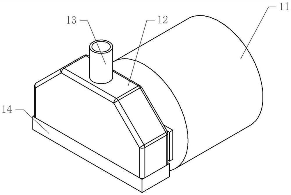
[0032] Basic as attached figure 1 , attached figure 2 , attached image 3 And attached Figure 4 As shown, a dust removal device for plate cutting includes a cover body 12 installed on the cutting machine, the upper part of the cover body 12 is trapezoidal, the lower part of the cover body 12 is rectangular, and the upper part of the cover body 12 is connected with a gas pipe 13 , the air pipe 13 communicates with a negative pressure machine, and the lower part of the cover body 12 is fixedly connected with a brush 14 .

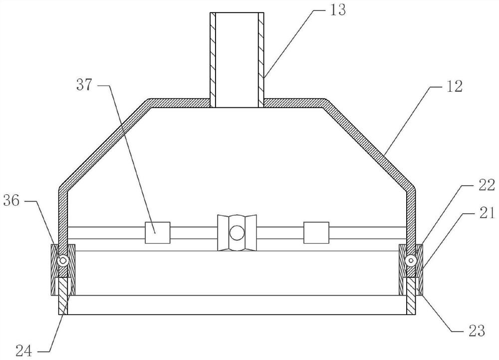
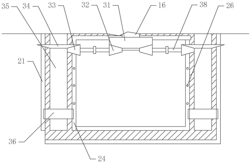
[0033] In this embodiment, both sides of the cover body 12 are provided with a cleaning mechanism. The cleaning mechanism includes a rotating shaft 35 that is rotatably connected to the cover body 12. One end of the rotating shaft 35 is fixedly connected with a half gear 36 (incomplete gear) with a coaxial bolt. Both sides of the gear 36 are provided with L-shaped cleaning plates, which are vertically slidably connected to the cover body 12, wherein one c...

Embodiment 2

[0043] The difference between embodiment two and embodiment one is that, as attached Figure 5 As shown, the connecting portion 37 is hollow, and the connecting portion 37 is provided with a cam 373 coaxially fixedly connected with the connecting shaft 38, and the upper part of the connecting portion 37 is provided with a push shaft 372 vertically slidingly connected with the cover body 12. The push shaft 372 Against the cam 373, an L-shaped scraper 371 is vertically slidably connected to the top of the push shaft 372. The horizontal section of the scraper 371 is offset against the push shaft 372, and the vertical section of the scraper 371 extends into the air pipe 13 and is in contact with the air pipe 13. Trachea 13 is close together.

[0044] The specific implementation process is as follows:

[0045] Since the dust will partially adhere to the air pipe 13, the excessive accumulation of powder will cause the diameter of the air pipe 13 to decrease. Therefore, in this embo...


PUM


Abstract

The invention belongs to the technical field of plate processing powdered scrap removing equipment, and provides a powdered scrap removing device for plate cutting, which comprises a cover body and a negative pressure machine communicated with the cover body, cleaning mechanisms are arranged on both sides of the cover body, each cleaning mechanism comprises a rotating shaft rotationally connected with the cover body, and one end of each rotating shaft is coaxially and fixedly connected with a half gear. The other end of the rotating shaft is connected with a transmission mechanism; cleaning plates in vertical sliding connection with the cover body are arranged on the two sides of the half gear, one cleaning plate is located on the inner side of the cover body, the other cleaning plate is located on the outer side of the cover body, a reset piece fixedly connected with the cover body is arranged on the cleaning plate located on the inner side, and racks meshed with the half gear are fixedly connected to the cleaning plates; a pressing plate is fixedly connected to the lower portion of the rack, and a plurality of cleaning protrusions are fixedly connected to the pressing plate. The brush cleaning device is simple in structure, a brush is cleaned, and the brush is extruded so that the probability of deformation of bristles of the brush can be reduced.

Description

technical field [0001] The invention belongs to the technical field of sheet material processing dust removal equipment, and in particular relates to a dust removal device for sheet material cutting. Background technique [0002] At present, a large amount of dust will be produced when cutting the board, and the dust will diffuse in the air, which not only affects the environment of the factory, but also easily causes a dust explosion when the dust reaches a certain concentration. of dust for processing. [0003] The current general treatment method is to use a fan to transport the powder to the outside of the factory to reduce the concentration of the powder. However, this method cannot accurately send the powder away. At the same time, because the fan acts on the entire factory, the powder The dust removal effect is not good. [0004] In order to accurately remove the dust and prevent the dust from entering the factory environment, a dust removal device is generally inst...

Claims


Application Information

Patent Timeline
Patent Type & Authority Applications(China)
IPC IPC(8): B27G3/00B28D7/02B23Q11/00
CPCY02P70/10
Inventor 罗庭
Owner 重庆市德统家居有限公司
Why Eureka
Try Eureka