Residual material removing mechanism for liquid crystal panel

A liquid crystal panel and residual material technology, which is applied in the field of liquid crystal panel automation equipment, can solve problems such as increasing processing time, reducing production takt, and having no residual material, and achieves the effects of reducing fragmentation, improving production efficiency, and protecting fingers

Pending Publication Date: 2022-04-01
WUXI SHANGSHI ELECTRONICS TECH
View PDF19 Cites 1 Cited by
  • Summary
  • Abstract
  • Description
  • Claims
  • Application Information

AI Technical Summary

Problems solved by technology

However, since TFT and CF are made on the same size glass substrate, the electrodes on the TFT will be covered by CF, resulting in the inability to complete IC bonding. It is necessary to cut off the CF glass area covering the TFT electrodes, that is, the residual material
[0003] At present, most of the equipment does not have residual material removal effect detection components. Generally, the success rate of residual material removal is improved by multiple blowing methods, and then the residual material removal effect is detected by manual sampling.
Manual detection is slow and easy to miss
With the thinning of the LCD panel and the increase in size, the difficulty of manual inspection is increased, or some residual materials cannot be removed after multiple air blowing, and it will increase the processing time, reduce the production cycle, and affect the production capacity.
Some undiscovered residues flow to downstream processes, causing further loss of materials and man-hours

Method used


Image

  • Residual material removing mechanism for liquid crystal panel
  • Residual material removing mechanism for liquid crystal panel
  • Residual material removing mechanism for liquid crystal panel

Examples


Embodiment Construction

[0019] Next, the technical solutions in the embodiments of the present invention will be described in connection with the drawings of the embodiments of the present invention, and it is understood that the described embodiments are merely the embodiments of the present invention, not all of the embodiments. Based on the embodiments of the present invention, all other embodiments obtained by those of ordinary skill in the art are in the range of the present invention without making creative labor premise.

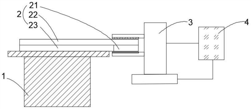
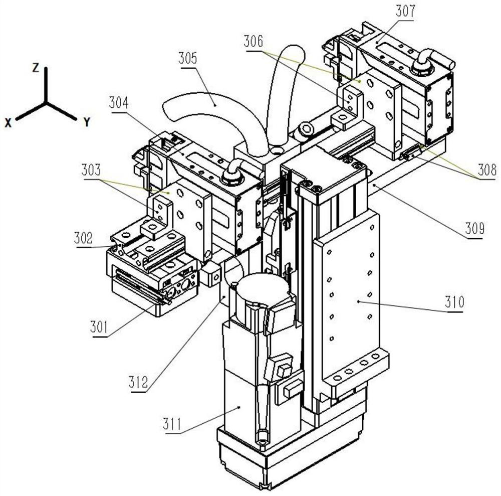
[0020] refer to Figure 1 to 3 , The removal sheave mechanism of a liquid crystal panel includes a stage 1, characterized in that the stage 1 is used to secure the liquid crystal panel 2, the removal sheave assembly 3 drives the jaw assembly A304 from the first module 318 A304 Move in the z-axis direction, the first module 311 is fixed to the machine through the module fixing plate 310, the jaw assembly A304 is fixed to the linker 302 by the first fixed block group 303, the chain...


PUM

PropertyMeasurementUnit
Shore hardnessaaaaaaaaaa
friction coefficientaaaaaaaaaa

Abstract

According to the technical scheme, the residual material removing mechanism is characterized in that the residual material removing mechanism comprises an objective table and a residual material removing assembly, the objective table is used for fixing the liquid crystal panel, and the objective table can be of a turnover platform or a robot arm or other structures; the residual material removing assembly removes residual materials on one side of a circuit layer of the liquid crystal panel through a clamping jaw assembly A. The clamping jaw assembly A moves in the Z-axis direction under dragging of the first module and moves in the Y-axis direction under dragging of the Y-axis controller. The upper clamping jaw and the lower clamping jaw drag the upper friction part and the lower friction part to clamp the residual material area of the liquid crystal display panel when relatively translating under the control of the servo control system, and can be suitable for the liquid crystal display panels with different thickness specifications; and under dragging of the Y-axis controller, different friction forces are generated on the upper surface and the lower surface of the liquid crystal panel residual material area, meanwhile, airflow with certain pressure is applied to the separation area through the air pipe, and therefore the cut liquid crystal panel residual materials are separated.

Description

Technical field [0001] The removal sheave mechanism of the liquid crystal panel of the present invention belongs to the field of liquid crystal panel automation equipment. Background technique [0002] Materials such as liquid crystal panels require photolithographic electrodes, TFT (Thin Film Transistor, thin film transistors), and CF (Color Film, color filter), grout, IC (Integrated Circuit, Integrated Circuit) binding. The electrodes are etched on TFT glass by means of photolithography, and the IC needs to be bound to the electrode to complete the lighting control operation. However, since TFT and CF are made on the glass substrate of the same size, the electrodes on the TFT are covered by CF, resulting in the unable to complete the IC binding, requiring removal of CF glass regions covering on the TFT electrode, i.e., sheaves. [0003] At present, most of the equipment has no residual removal effect detection assembly, which generally improves the success rate of residual mate...

Claims


Application Information

Patent Timeline
Patent Type & Authority Applications(China)
IPC IPC(8): G02F1/13G02F1/1337
Inventor 张俊烽霍辉夏爽孙一鸣贾磊李杨杨水源李郎炳林晓东
Owner WUXI SHANGSHI ELECTRONICS TECH
Why Eureka
Try Eureka