Production equipment for multi-material and multi-specification glass bottles
A glass bottle, multi-specification technology, applied in glass production, glass molding, glass manufacturing equipment, etc., can solve problems such as efficiency loss and material waste, and achieve the effect of saving mold costs
- Summary
- Abstract
- Description
- Claims
- Application Information
AI Technical Summary
Problems solved by technology
Method used
Image
Examples
Embodiment 1
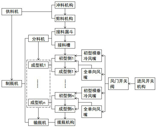
[0052] like figure 1 It is shown that the production equipment of the multi -materials and multi -specified glass bottle is the same as the existing technology, including the material supply machine and the bottle making machine. The supplier includes the punching mechanism and the shear mechanism. The melting state glass material is sent to the bottle making machine after the punching mechanism and the cutting mechanism. Common sense, I won't go into details here.
[0053] The bottle making machine includes the feeder, the molding machine and the bottle -mortar machine. Among them, the feeder includes the seasoning funnel and the seasoning groove. After the exposure groove is output, enter the molding machine. There are at least one molder setting, including the first side and the corresponding molding side in each molding machine. The glass drip -to -seasoning tank enters the initial model of the initial side of each molding machine. The first type of embryo is formed on the fir...
Embodiment 2
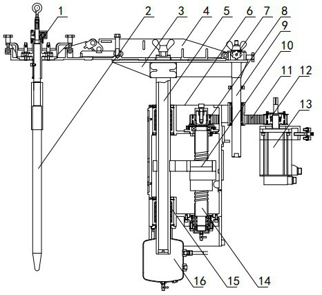
[0102] like Figure 18 The difference between the embodiments and Example 1 is that the length of the gas supply board 24 is further increased. There are four funnel 25 in the side of the air supply board 24, and the internal trachea 26 is at the same time as the internal air supply board 24 at the same time as the same as the air supply board 24 at the same time as the same as the at the same time as the air supply board 24 at the same time as the same as Four funnels were connected by 25, and multiple drops were achieved. It can also be placed in the interior of the air supply board 24 as needed.
Embodiment 3
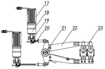
[0104] The difference between this embodiment and Example 1 is that the structure of the shear mechanism is different. like Figure 19 In this example, in this embodiment, the cutting mechanism includes a scissor servo motor 17, cutting servo motor 17, and the input terminal of cutting reducer 18. The transmission set 19 fixes one end of the cutting connecting rod 20, the other end of the cut connecting rod 20 is hinged in the middle of one of the scissors 22 of the two scissors arm 22, and one end of the two scissors arm 22 is set. 105, two cut gears 105. At the end of the two ends of the two scissors, there are scissors 23, and the cutting mouth of the scissors 23 with two scissors of the scissors of the two scissors.
[0105] Cut the servo motor 17 During the cutting reducer 18 and the eccentric transmission set 19 to drive the cut connecting rod 20 to move, the cut connecting rod 20 further drives the corresponding scissors arm 20 to move, the scissors arm 20 rotation of the ro...
PUM
 Abstract
Description
Claims
Application Information
 - R&D
- Intellectual Property
- Life Sciences
- Materials
- Tech Scout
- Unparalleled Data Quality
- Higher Quality Content
- 60% Fewer Hallucinations
Browse by: Latest US Patents, China's latest patents, Technical Efficacy Thesaurus, Application Domain, Technology Topic, Popular Technical Reports.
© 2025 PatSnap. All rights reserved.Legal|Privacy policy|Modern Slavery Act Transparency Statement|Sitemap|About US| Contact US: help@patsnap.com


