Supercharge Your Innovation With Domain-Expert AI Agents!

Improved amphibious excavator

An amphibious, excavator technology, applied in mechanically driven excavators/dredgers, etc., can solve the problems of lateral limit failure, affecting the transmission of the force between the floating box and the beam, and the wear of the hole wall of the floating box. The effect of swing and friction, shortening maintenance frequency, and avoiding safety accidents

Pending Publication Date: 2022-04-05
建湖宝迪工程机械有限公司
View PDF0 Cites 0 Cited by
  • Summary
  • Abstract
  • Description
  • Claims
  • Application Information

AI Technical Summary

Problems solved by technology

During long-term use, frequent friction between the wall of the beam and the inner hole of the pontoon causes the gap between the hole and shaft to expand. The main result is the wear of the pontoon wall, which eventually causes the pin to break or fall off. Transmission of force between the pontoon and the beam;
[0005] 2. In the process of installing the pin, it is necessary to align the cross beam with the pin hole of the pontoon, or make it a pin hole after insertion, which increases the difficulty of installing the pin. Rotation, twisting and deformation occur between the holes of the pontoons, it is extremely difficult to install new pins, and installation and disassembly are very difficult; the current solution is to weld iron hooks between the two pontoons and connect them with chains to limit the lateral movement of the pontoons ;
[0006] 3. After the pin breaks or falls off, if it is not found in time, the pontoon will come out from the beam, causing a safety accident with serious consequences;
[0007] 4. When carrying a large-tonnage excavator, it is necessary to add a pontoon outside the existing pontoon. The connection structure between the existing beam and the pontoon will affect the newly added pontoon, and it needs to be removed, which is more troublesome

Method used


Image

  • Improved amphibious excavator
  • Improved amphibious excavator
  • Improved amphibious excavator

Examples


Embodiment Construction

[0033] The specific content of the present invention will be described in detail below in conjunction with the accompanying drawings and specific embodiments.

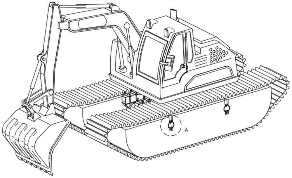
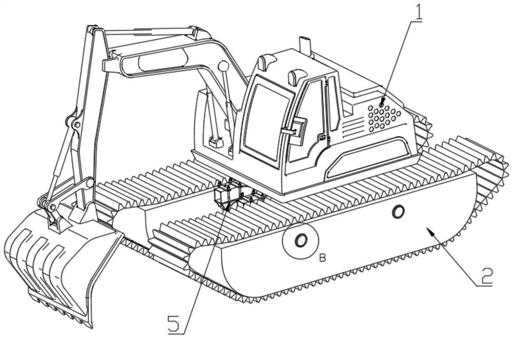
[0034] Such as image 3 , 4 As shown, an improved amphibious excavator includes a body 1, a vehicle frame 5, a beam 3, and a pontoon 2. The body 1 is installed in the center of the vehicle frame 5, and the bracket of the vehicle frame 5 is connected to the vehicle frame through a U-shaped hoop. Beam 3 connection. Floating tank 2 has more than two, is arranged on vehicle frame 5 both sides symmetrically. Described beam 3 has two, runs through buoyancy tank 2.

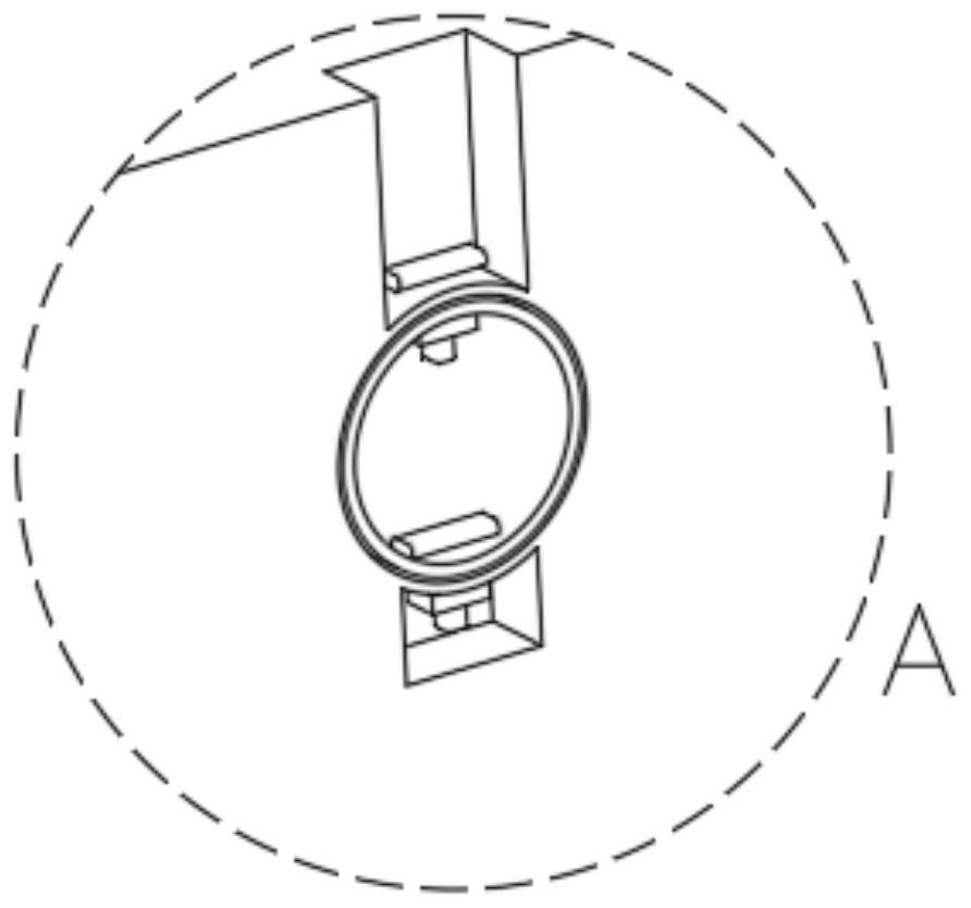
[0035] Such as Figure 5 , 6 , 7 and 8, it also includes a first fixed frame 6, a second fixed frame 7, and a latch block 8, and the first fixed frame 6 and the second fixed frame 7 include a cavity surrounded by plates. An insertion slot is provided on the cavity, and the first fixed frame 6 and the second fixed frame 7 are movably connected by a bolt bloc...


PUM


Abstract

The improved amphibious excavator comprises a machine body, a vehicle frame, a cross beam and a buoyancy tank and further comprises a first fixing frame, a second fixing frame and a plug pin block, the first fixing frame and the second fixing frame comprise cavities defined by plates, inserting grooves are formed in the cavities, and the first fixing frame and the second fixing frame are movably connected through the plug pin block; the bolt block is provided with two symmetrical embedded blocks, a groove is formed between the embedded blocks, and the two embedded blocks penetrate through the inserting grooves of the first fixing frame and the second fixing frame respectively and are embedded into the cavities of the first fixing frame and the second fixing frame. The four first fixing frames are symmetrically installed on the upper portion of the inner side face of the buoyancy tank in a pairwise mode, and the first fixing frames are arranged on the upper portions of the installation holes. The four second fixing frames are symmetrically installed on the upper portion of the outer side face of the frame, and the second fixing frames are arranged on the upper portion of the cross beam. The connecting mode of the buoyancy tank and the cross beam is simple and convenient, the stability is higher, the rigidity is better, the maintenance frequency is shortened, and safety accidents are avoided.

Description

technical field [0001] The invention belongs to the field of special excavators, and in particular relates to an improved amphibious excavator. Background technique [0002] The amphibious excavator not only has the functions of a general-purpose excavator, but also has the characteristics of ultra-low grounding specific pressure and water buoyancy. The amphibious excavator has the advantages of high buoyancy, which can ensure the normal operation and safe floating of the whole machine in muddy water. In actual construction, it can drive in water, swamps and soft ground without any other auxiliary equipment consignment, and can enter and exit waters by itself by configuring the engine. [0003] But existing amphibious excavator chassis is connected with buoyancy box as specification attached figure 1 As shown, the excavator is connected with the chassis, and the chassis is installed on the frame. The frame is connected with two tubular beams through hoops. The beams pass t...

Claims


Application Information

Patent Timeline
IPC IPC(8): E02F3/28E02F3/34E02F3/36E02F3/40
Inventor 迮甲玉
Owner 建湖宝迪工程机械有限公司
Features
  • R&D
  • Intellectual Property
  • Life Sciences
  • Materials
  • Tech Scout
  • Unparalleled Data Quality
  • Higher Quality Content
  • 60% Fewer Hallucinations
Learn More