
Synchronous powder forming machine

A molding machine and molding mechanism technology, applied in the direction of turbines, engine components, other manufacturing equipment/tools, etc., can solve problems such as inability to suppress other shapes, uneven force at the center point, poor efficiency, etc., and achieve high practical value and economic value , high processing progress and efficiency, uniform center strength

Pending Publication Date: 2022-04-08
贵阳立特精密机械有限公司
View PDF0 Cites 0 Cited by
  • Summary
  • Abstract
  • Description
  • Claims
  • Application Information

AI Technical Summary

Problems solved by technology

[0003] Existing tantalum block forming machines generally use horizontal tantalum block forming machines and vertical tantalum block forming machines. During production, the left and right or upper and lower push rods are driven by servo motors to press tantalum powder into cubes, which cannot be pressed into blocks. Other shapes, and the tantalum block pressed in this working mode, the force at the center point is not uniform enough, and the efficiency is poor

Method used


Image

  • Synchronous powder forming machine
  • Synchronous powder forming machine
  • Synchronous powder forming machine

Examples


Embodiment Construction

[0025] In order to make the purpose, technical solutions and advantages of the embodiments of the present invention more clear, various implementation modes of the present invention will be described in detail below in conjunction with the accompanying drawings. However, those of ordinary skill in the art can understand that, in each implementation manner of the present invention, many technical details are provided for readers to better understand the present application. However, even without these technical details and various changes and modifications based on the following implementation modes, the technical solution claimed in this application can also be realized. The division of the following embodiments is for the convenience of description, and should not constitute any limitation to the specific implementation of the present invention, and the various embodiments can be combined and referred to each other on the premise of no contradiction.

[0026] The first embodi...


PUM


Abstract

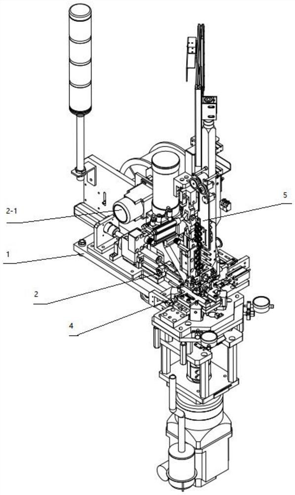
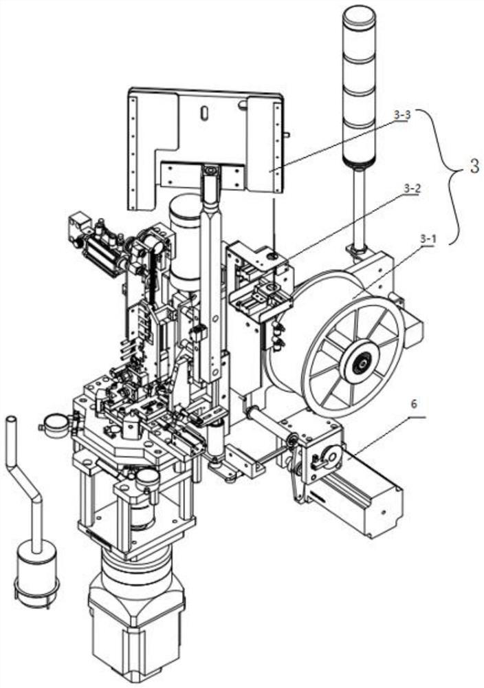
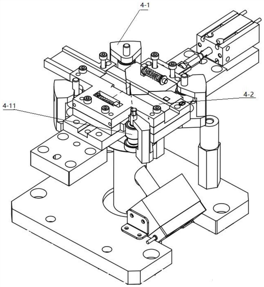
The invention discloses a powder synchronous forming machine, which can complete forming action while embedding a metal wire in powder, and comprises a powder feeding mechanism, a wire feeding mechanism, a forming mechanism, a straightening mechanism, a cutting mechanism and a bottom plate, the forming mechanism is arranged in the middle of the bottom plate, and the powder feeding mechanism is connected to the tail part of the bottom plate. A wire feeding mechanism used for conveying tantalum wires is arranged on one side of the powder feeding mechanism, a straightening mechanism is vertically installed above the forming mechanism, and a cutting-off mechanism used for cutting off the tantalum wires is installed below the same side of the wire feeding mechanism through a lead screw. The forming mechanism comprises a synchronous extrusion forming die arranged in the middle of the bottom plate and a driving shaft surrounding and wrapping the synchronous extrusion forming die. The shape of the synchronous extrusion forming die can be replaced according to a product needing to be machined, the purpose of machining various polygonal shapes is achieved, one-time forming is achieved, the machining efficiency is higher, the product density is uniform, and the size and precision errors are small.

Description

technical field [0001] The invention belongs to the technical field of processing equipment for tantalum blocks in tantalum capacitors, and in particular relates to a powder synchronous molding machine. Background technique [0002] The processing technology of the tantalum block of the existing military tantalum capacitor is as follows: put an appropriate amount of tantalum powder into the mold cavity, press the tantalum powder into a certain shape through the mold, and insert a tantalum wire of a specified length into the tantalum block during the pressing process. . [0003] Existing tantalum block forming machines generally use horizontal tantalum block forming machines and vertical tantalum block forming machines. During production, the left and right or upper and lower push rods are driven by servo motors to press tantalum powder into cubes, which cannot be pressed into blocks. Other shapes, and the tantalum block that is pressed out under this working mode, its centr...

Claims


Application Information

Patent Timeline
IPC IPC(8): B22F3/03B22F5/00B22F7/08B21F1/02B21F11/00
Inventor 郭昊灵
Owner 贵阳立特精密机械有限公司
Features
  • Generate Ideas
  • Intellectual Property
  • Life Sciences
  • Materials
  • Tech Scout
  • Unparalleled Data Quality
  • Higher Quality Content
  • 60% Fewer Hallucinations
Learn More