

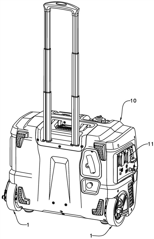
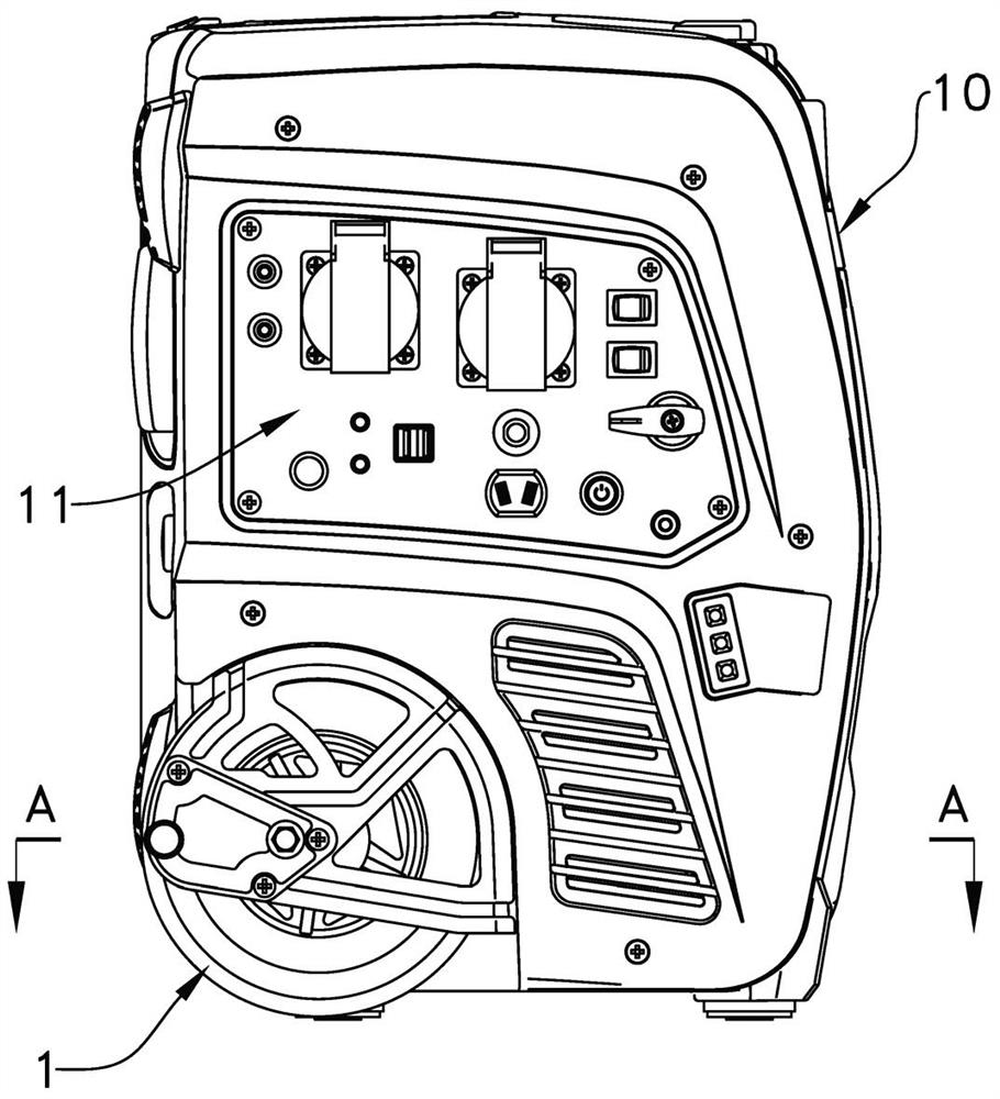
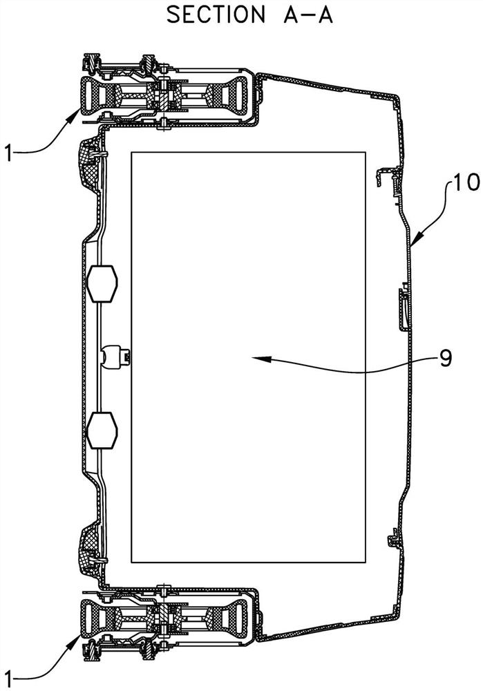
Roller device of power generation equipment
A technology of power generation equipment and rollers, which is applied in the direction of mechanical equipment, engine frames, casters, etc., can solve the problems of easy bumping into the ground, large diameter rollers, poor adaptability to road conditions, etc., and achieve good mobility and excellent overall size Small, low-cost effect
- Summary
- Abstract
- Description
- Claims
- Application Information
AI Technical Summary
Problems solved by technology
Method used
Image

Examples
Embodiment Construction
[0038] The present invention will be described in detail below with reference to the accompanying drawings and in combination with embodiments.
[0039] In this embodiment, the main body of the power generation equipment can mainly include the following four categories of products: Generator Set driven by an internal combustion engine, Portable Power Station with energy storage, Solar Power Station, And welding machine (Welding Machine). The generator set is mainly composed of an engine, a generator and an electronic control system. The generator outputs electric energy under the drive of the engine, and can convert the chemical energy of fuel or gas into electrical energy. The digital generator also includes an inverter, which can convert the intermediate-frequency alternating current output by the generator into a power-frequency alternating current with stable voltage at various speeds. The energy storage mobile power supply mainly includes batteries, inverters and control...
PUM
 Abstract
Description
Claims
Application Information