Power transmission line monitoring device and method based on fiber bragg grating

A fiber grating and monitoring device technology, applied in circuit devices, measuring devices, measuring device casings, etc., can solve the problems of strong electromagnetic environment intrusion, insufficient power supply reliability, and data transmission reliability challenges, and achieve the effect of simple and compact structure.

Pending Publication Date: 2022-04-08
CHINA ELECTRIC POWER RES INST +5
View PDF0 Cites 0 Cited by
  • Summary
  • Abstract
  • Description
  • Claims
  • Application Information

AI Technical Summary

Problems solved by technology

The existing wire temperature monitoring sensors are mainly based on wireless contact electronic temperature measurement. They are installed at the end of the wire, and a special clamping structure needs to be designed to closely cooperate with the wire. Stress concentration occurs, and improper installation will damage the wires; the power supply of this type of sensor is usually combined with battery and solar power, and the reliability of the power supply for long-term operation is insufficient; The device must be specially designed for anti-electromagnetic interference, which is difficult to design
Nevertheless, the reliability of data transmission is still seriously challenged

Method used


Image

  • Power transmission line monitoring device and method based on fiber bragg grating
  • Power transmission line monitoring device and method based on fiber bragg grating
  • Power transmission line monitoring device and method based on fiber bragg grating

Examples


Embodiment 1

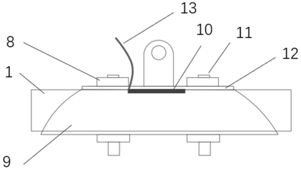
[0032] A fiber grating-based power transmission line monitoring device provided by the present invention has a schematic structural diagram as shown in figure 1 As shown, including: wire clamp 3 and wire temperature monitoring unit 10;

[0033] The wire clamp 3 includes a wire clamp cover 12; the wire temperature monitoring unit 10 is embedded inside the wire clamp cover 12 and is in contact with the tested wire 1;

[0034] The wire temperature monitoring unit 10 is used to sense the temperature change of the wire under test 1 and generate an optical signal; it is also used to send the optical signal.

[0035] The wire temperature monitoring unit 10 is integrated with the wire clamp cover 12 , which is realized by embedding a fiber optic grating sensor in the wire clamp cover 12 . The wire clip cover 12 is made of steel with a groove in the middle for embedding the wire temperature monitoring unit 10 .

[0036] The clamp cover 12 is tightly pressed between the tested wire 1 ...

Embodiment 2

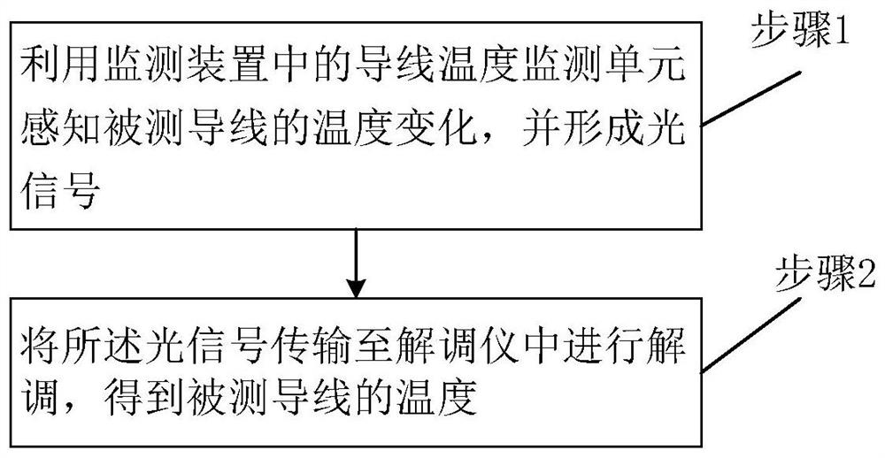
[0042] Based on the same inventive concept, the present invention also provides a fiber grating-based transmission line monitoring method, such as image 3 shown, including:

[0043] Step 1: Use the wire temperature monitoring unit 10 in the monitoring device to sense the temperature change of the wire 1 under test, and form an optical signal;

[0044] Step 2: Transmitting the optical signal to the demodulator 7 for demodulation to obtain the temperature of the tested wire 1 .

[0045] Step 2 specifically includes:

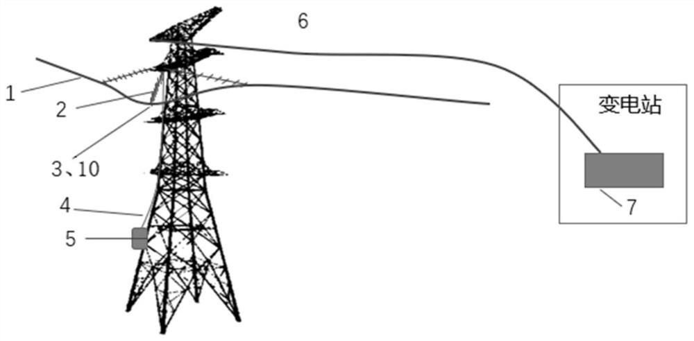
[0046] Through the pigtail 13 of the wire temperature monitoring unit 10, the optical signal is transmitted through the optical fiber led by the insulator 2 and the connecting optical fiber 4 into the optical fiber splice box 5 on the tower, and then the optical signal is transmitted to the demodulator located in the substation through the OPGW 6 instrument 7, the optical signal is demodulated by the demodulator 7 to obtain the temperature of the wire 1.

[004...


PUM


Abstract

The invention provides a fiber grating-based power transmission line monitoring device and method. The fiber grating-based power transmission line monitoring device comprises a wire clamp (3) and a wire temperature monitoring unit (10), the wire clamp (3) comprises a wire clamp cover plate (12); the wire temperature monitoring unit (10) is embedded in the inner side of the wire clamp cover plate (12) and is in contact with a measured wire (1); the wire temperature monitoring unit (10) is used for sensing the temperature change of the measured wire (1) and forming an optical signal; the optical transmitter is also used for transmitting the optical signal; the wire temperature monitoring unit is directly embedded on the wire clamp cover plate (12), the original form of a circuit component is not changed, the structure is simple and compact, and the wire (1) is not damaged; the fiber bragg grating sensing unit is used as a wire temperature monitoring unit to monitor the temperature of the wire (1), field power supply is not needed, and the problem of insufficient reliability of long-term operation power supply is avoided; the fiber bragg grating sensing unit is not affected by electromagnetic interference, can be installed on a line for a long time, and operates reliably.

Description

technical field [0001] The invention belongs to the field of power transmission line state monitoring, and in particular relates to a power transmission line monitoring device and method based on an optical fiber grating. Background technique [0002] The ambient temperature around the transmission tower and the temperature of the conductor are one of the important indicators for transmission line monitoring. The existing wire temperature monitoring sensors are mainly based on wireless contact electronic temperature measurement. They are installed at the end of the wire, and a special clamping structure needs to be designed to closely cooperate with the wire. Stress concentration occurs, and improper installation will damage the wires; the power supply of this type of sensor is usually combined with battery and solar power, and the reliability of the power supply for long-term operation is insufficient; The device must be specially designed for anti-electromagnetic interfer...

Claims


Application Information

Patent Timeline
Patent Type & Authority Applications(China)
IPC IPC(8): G01R31/08G01R1/04G01R15/24G01K11/3206H02J50/30
Inventor 姬昆鹏袁兆祥吴发献汉京善方炯韩嘉佳汪自翔刘彬赵彬杨加伦张立春展雪萍杨知李孟轩李鹏李丹煜张国强刘畅高昱峰杨俊
Owner CHINA ELECTRIC POWER RES INST
Why Eureka
Try Eureka