Close-range detector

A detector and short-distance technology, which is applied in the field of detectors, can solve problems such as machine crashes and signal interference, and achieve the effects of increasing signal strength, improving the noise-to-noise ratio, and reducing noise and light

Pending Publication Date: 2022-04-08
YEJIA OPTICAL TECH GUANGDONG CORP
View PDF8 Cites 2 Cited by
  • Summary
  • Abstract
  • Description
  • Claims
  • Application Information

AI Technical Summary

Problems solved by technology

There may be two consequences of this kind of interference: the first case is overestimation, which will cause the original height difference to be very low and can be crossed, but it is mistakenly detected as a large height difference and retreats; the second case is underestimation , originally the height difference is high, the signal is affected by stray light and is interfered, so it is misjudged as a low height difference, causing the machine to crash

Method used


Image

  • Close-range detector
  • Close-range detector
  • Close-range detector

Examples


Embodiment 1

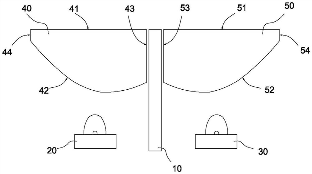
[0043] Please refer to Figure 1 to Figure 5 .

[0044] A kind of close-range detector, comprises black baffle 10, the emission source 20 that is positioned at black baffle 10 both sides, receiving chip 30, the first lens 40 that is positioned at emission source 20 upper side, the second lens 40 that is positioned at receiving chip 30 upper side The lens 50, the emission source 20 adopts a light emitting diode;

[0045] The first lens 40 has a first light exit surface 41 close to the object side, a first light incident surface 42 close to the emission source 20 side, and a first side surface 43 close to the black baffle 10 baffle side. Surface 41 is a plane;

[0046] The second lens 50 has a second light incident surface 51 close to the object side, a second light exit surface 52 close to the receiving chip 30 side, a second side surface 53 close to the black baffle 10 side, the second light incident surface 51 is a plane;

[0047] The light emitted by the emission source 20...

Embodiment 2

[0058] Please refer to Figure 8 .

[0059] In this embodiment, an included angle γ is formed between the first side 43 and the black baffle 10 1 , the angle γ is formed between the second side 53 and the black baffle 10 2 , gamma 1 with gamma 2 Satisfy the following conditions: 0°1 = γ 2 <90°. The first side 43 is designed to a certain angle of inclination, so that the emitted stray light is absorbed by the black baffle plate 10 in the middle, thereby avoiding the emission of the stray light; the second side 53 is designed to have a certain angle of inclination, so that The incident light is deflected so that the light in the harmful visible area 84 cannot be received by the receiving chip 30 .

Embodiment 3

[0061] Please refer to Figure 9 .

[0062] In this embodiment, the end of the black baffle 10 on the object side is connected with a first baffle 11, and one end of the first baffle 11 extends to the side of the first light-emitting surface 41, so that the side of the first light-emitting surface 41 forms a black light-blocking The area can absorb the stray light emitted by the emission source 20, and the other end of the first baffle 11 extends to the side of the second light incident surface 51, so that a black light blocking area is formed on the side of the second light incident surface 51, so that The emitted stray light is absorbed.


PUM


Abstract

The invention provides a short-distance detector. The short-distance detector comprises a black baffle, an emission source, a receiving chip, a first lens and a second lens, light emitted by the emission source is refracted by the first lens, and an emission lighting area is formed on the upper side of the first lens; the emission illumination area and the receiving visible area have intersections, and a near-end intersection area, a maximum intersection area and a far-end intersection area are formed. According to the short-distance detector, the first lens and the second lens are additionally arranged on the upper side of the emission source and the upper side of the receiving chip respectively, the emission illumination area is formed on the upper side of the first lens, the receiving visible area is formed on the upper side of the second lens, and specific structures and parameters of all faces of the first lens and the second lens are designed. Therefore, the average intersected effective visible area of the emission illumination area and the receiving visible area is large under different obstacle distances, the energy utilization rate is improved, and the signal intensity is improved.

Description

technical field [0001] The invention relates to the technical field of detectors, in particular to a short-distance detector. Background technique [0002] In the field of robotics and vision, many technologies related to obstacle detection and avoidance have been developed that employ various types of distance sensors (e.g., lidar, radar, infrared, sonar) and cameras. These techniques consider a wide range of target objects to detect and estimate their relative distances. Mobile robots in indoor environments (such as sweeping robots) also need to perceive the indoor environment. They use various types of sensors to detect and measure the surrounding world and their own progress in it, including cliff sensors, Bump sensors, wall sensors, and optical encoders. Among them, the cliff detector is a necessary sensor, which will be used by related robots. It is used to sense the height of the steps. Each sensor consists of an infrared emitting tube (IR LED) and an infrared recei...

Claims


Application Information

Patent Timeline
Patent Type & Authority Applications(China)
IPC IPC(8): G01S17/02G01S17/93G01S7/481
Inventor 江程佘俊南基学
Owner YEJIA OPTICAL TECH GUANGDONG CORP
Why Eureka
Try Eureka