Power transmission and transformation ultrasonic partial discharge sensor and method thereof

An ultrasonic and sensor technology, applied in the field of power transmission and transformation ultrasonic partial discharge sensors, can solve the problems of inflexible networking mode, heavy maintenance workload, and large electromagnetic environment impact, and achieve the effect of intelligent maintenance and safe operation.

Pending Publication Date: 2022-04-12
NANJING ZHENGTU INFORMATION TECH CO LTD
View PDF7 Cites 1 Cited by
  • Summary
  • Abstract
  • Description
  • Claims
  • Application Information

AI Technical Summary

Problems solved by technology

[0004] Current situation: Before partial discharge occurs, the electric field force around the discharge point, the mechanical stress of the insulating medium and the particle force are in a relatively balanced state
The traditional operation inspection mode that relies on manual inspection has a huge workload, long inspection cycle, and low efficiency; defects cannot be found effectively and in a timely manner; human input costs are high, such as simple and repetitive mechanical tasks such as meter transcription and unpacking inspection occupy O&M A lot of time for personnel, ultrasonic partial discharge sensors are beneficial to reduce costs and increase efficiency; traditional online monitoring devices have complex structures, bulky volumes, and huge power consumption; they are greatly affected by the electromagnetic environment, the networking method is not flexible, and the maintenance workload is large

Method used


Image

  • Power transmission and transformation ultrasonic partial discharge sensor and method thereof
  • Power transmission and transformation ultrasonic partial discharge sensor and method thereof
  • Power transmission and transformation ultrasonic partial discharge sensor and method thereof

Examples


Embodiment Construction

[0033] The following will clearly and completely describe the technical solutions in the embodiments of the present invention with reference to the accompanying drawings in the embodiments of the present invention. Obviously, the described embodiments are only some, not all, embodiments of the present invention. Based on the embodiments of the present invention, all other embodiments obtained by persons of ordinary skill in the art without making creative efforts belong to the protection scope of the present invention.

[0034] In order to improve the power of equipment status management and control and the penetration of operation inspection management, the Internet of Things for Power Equipment takes the smart grid as the comprehensive application field of Internet of Things technology for power, and builds a pattern of innovation-driven, application-led, and coordinated development.

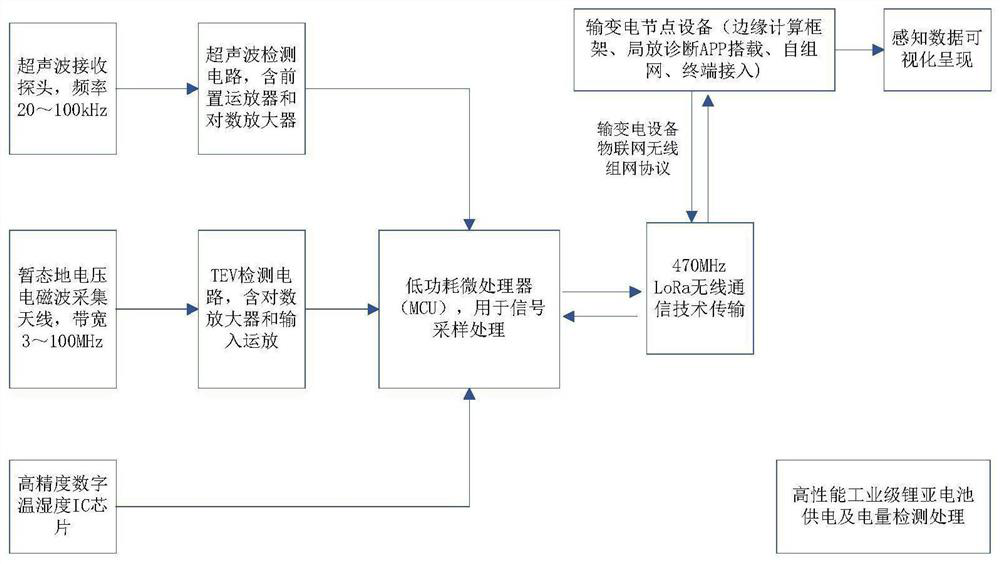
[0035] see figure 1 , the present invention provides a technical solution: an ultrasonic p...


PUM


Abstract

The invention discloses a power transmission and transformation ultrasonic partial discharge sensor and a method thereof. The power transmission and transformation ultrasonic partial discharge sensor comprises a processor, an ultrasonic receiving probe, a TEV transient ground voltage detection circuit and a digital temperature and humidity IC, the output end of the ultrasonic receiving probe is electrically connected with an ultrasonic detection circuit, a front operational amplifier and a logarithmic amplifier are arranged in the ultrasonic detection circuit, and the ultrasonic receiving probe is electrically connected with a processor and a TEV transient ground voltage detection circuit through the ultrasonic detection circuit. The TEV transient ground voltage detection circuit logarithmic amplifier and the input operational amplifier of the front arithmetic unit are connected to a power equipment internet of things management and application platform through a power APN security encryption channel by adopting a miniaturized integrated packaging cast aluminum shell and a magnetic type installation mode, and the partial discharge sensor senses data and visually displays the data. Partial discharge monitoring and early warning of electrical equipment such as a switch cabinet, a gas insulation totally-enclosed combined electric appliance, a transformer, a cable and the like are realized.

Description

technical field [0001] The invention relates to the technical field of power transmission and transformation automation, in particular to an ultrasonic partial discharge sensor for power transmission and transformation and a method thereof. Background technique [0002] When partial discharge occurs inside the insulation of power equipment, ultrasonic signals are accompanied by it. The sources of ultrasonic signals mainly include two types: 1. The violent impact of molecules in the discharge area will generate corresponding pressure. When the pressure changes in a pulsed manner with the partial discharge, ultrasonic waves will be formed, and will flow from the partial discharge point to the surface in the form of spherical waves. 2. In GIS and other equipment, free metal particles will do resonance-like motion under the action of electric field force, gravity and friction. When the particles collide with the metal shell, ultrasonic signals will also be generated and travel a...

Claims


Application Information

Patent Timeline
Patent Type & Authority Applications(China)
IPC IPC(8): G01R31/12
Inventor 费章君操星叶曙光万尚军于文学管相东符建辉邓海波沈泉龙
Owner NANJING ZHENGTU INFORMATION TECH CO LTD
Why Eureka
Try Eureka