Supercharge Your Innovation With Domain-Expert AI Agents!

Laser radar collimation device

A laser radar and collimation technology, applied in the direction of installation, optics, optical components, etc., can solve the problems of increasing the size of the laser radar, increasing the difficulty and cost of radar assembly, increasing the complexity of the radar, etc., to improve the collimation performance, Effect of short focal length and improved collimation ability

Inactive Publication Date: 2022-04-12
HANGZHOU HONG JING DRIVE CO LTD
View PDF3 Cites 0 Cited by
  • Summary
  • Abstract
  • Description
  • Claims
  • Application Information

AI Technical Summary

Problems solved by technology

[0004] The purpose of the embodiment of the present application is to propose a laser radar collimation device to solve the problems of increasing the complexity of the radar, increasing the size of the laser radar, and increasing the difficulty and cost of radar assembly in the existing laser radar collimation system

Method used


Image

  • Laser radar collimation device
  • Laser radar collimation device

Examples


Embodiment Construction

[0024] Reference herein to an "embodiment" means that a particular feature, structure, or characteristic described in connection with the embodiment can be included in at least one embodiment of the present application. The occurrences of this phrase in various places in the specification are not necessarily all referring to the same embodiment, nor are separate or alternative embodiments mutually exclusive of other embodiments. It is understood explicitly and implicitly by those skilled in the art that the embodiments described herein can be combined with other embodiments.

[0025] In order to enable those skilled in the art to better understand the solutions of the present application, the technical solutions in the embodiments of the present application will be clearly and completely described below in conjunction with the accompanying drawings.

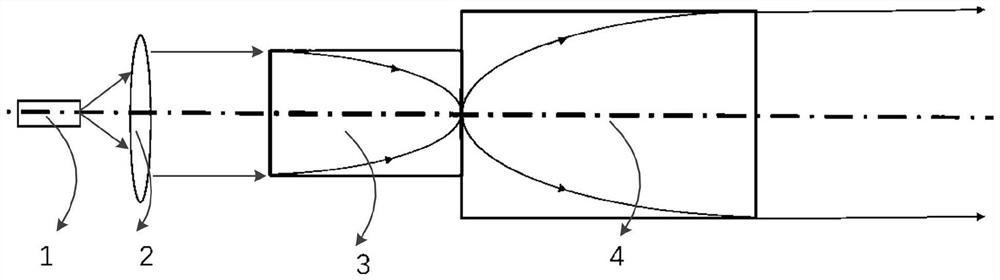
[0026] Please refer to figure 1 , the present application provides an embodiment of a laser radar collimation device, and the ...


PUM


Abstract

The invention belongs to the technical field of laser ranging, and relates to a laser radar collimating device which comprises a laser, and a positive lens, a first self-focusing lens and a second self-focusing lens are sequentially arranged in the light source emitting direction of the laser. Wherein a light source emission point of the laser is located at an object space focus position of the positive lens; the positive lens is used for collimating light emitted by the laser into parallel laser at a time; the focus of the first self-focusing lens and the focus of the positive lens are located on the same horizontal line, and the first self-focusing lens is used for converging the parallel laser from the incident plane of the first self-focusing lens to the emergent plane of the first self-focusing lens to form point laser; the focus of the second self-focusing lens and the focus of the first self-focusing lens are located on the same horizontal line, and the second self-focusing lens is used for secondarily collimating the point laser from the incident plane of the first self-focusing lens to the emergent plane to form parallel laser. By adopting the first self-focusing lens and the second self-focusing lens, the collimation capability of the laser radar can be improved, and the size of the laser radar can be effectively reduced.

Description

technical field [0001] The present application relates to the technical field of laser ranging, in particular to a laser radar collimation device. Background technique [0002] The laser radar technology actively emits a laser beam, irradiates the measured object, forms a diffuse reflection echo, and receives the echo by the receiving system; by measuring the time difference between the laser emission time and the echo reception time, the laser radar and the measured object can be obtained. distance information. Because the laser has the advantages of high repetition frequency, small laser spot, concentrated energy, and good directivity. This enables the laser radar to realize long-distance and high-precision measurement of the measured object. The 3D environment measurement and perception of lidar has important civil and military application value. In advanced driver assistance systems (ADAS) and automatic driving systems, spatial distance measurement and three-dimension...

Claims


Application Information

Patent Timeline
IPC IPC(8): G02B7/09G02B7/06G01S7/481
Inventor 寿翔常健忠
Owner HANGZHOU HONG JING DRIVE CO LTD
Features
  • R&D
  • Intellectual Property
  • Life Sciences
  • Materials
  • Tech Scout
  • Unparalleled Data Quality
  • Higher Quality Content
  • 60% Fewer Hallucinations
Learn More