Fault diagnosis method and device and electronic equipment

A fault diagnosis and fault technology, applied in the field of fault diagnosis, which can solve problems such as limited help, influence on the accuracy of diagnosis results, and inability to guarantee the accuracy of test results.

Pending Publication Date: 2022-04-12
北京智能建筑科技有限公司
View PDF0 Cites 6 Cited by
  • Summary
  • Abstract
  • Description
  • Claims
  • Application Information

AI Technical Summary

Problems solved by technology

At present, most of the maintenance personnel rely on their own experience and product manuals to deal with the failure of building mechanical and electrical equipment. Through manual operation and thinking about maintenance failures, the maintenance efficiency is heavily dependent on the technical ability and experience of the maintenance personnel.
As far as fault diagnosis of building electrical systems in the past is concerned, due to the limitations of traditional concepts and technical levels, most of them choose to use manual detection, which requires relatively high manpower, material and financial resources, and the accuracy of the detection results cannot be guaranteed.
Although the failure technology of building mechanical and electrical equipment is constantly being updated, overall, the stability of the system operation will still be affected by various factors and failures will occur, and the accuracy of the diagnosis results is relatively low, which can provide limited help for troubleshooting.
In addition, in the implementation of all fault diagnosis technologies, there are some algorithms that cannot meet the actual needs, and have a certain impact on the accuracy of diagnosis results.

Method used


Image

  • Fault diagnosis method and device and electronic equipment
  • Fault diagnosis method and device and electronic equipment
  • Fault diagnosis method and device and electronic equipment

Examples


Embodiment 1

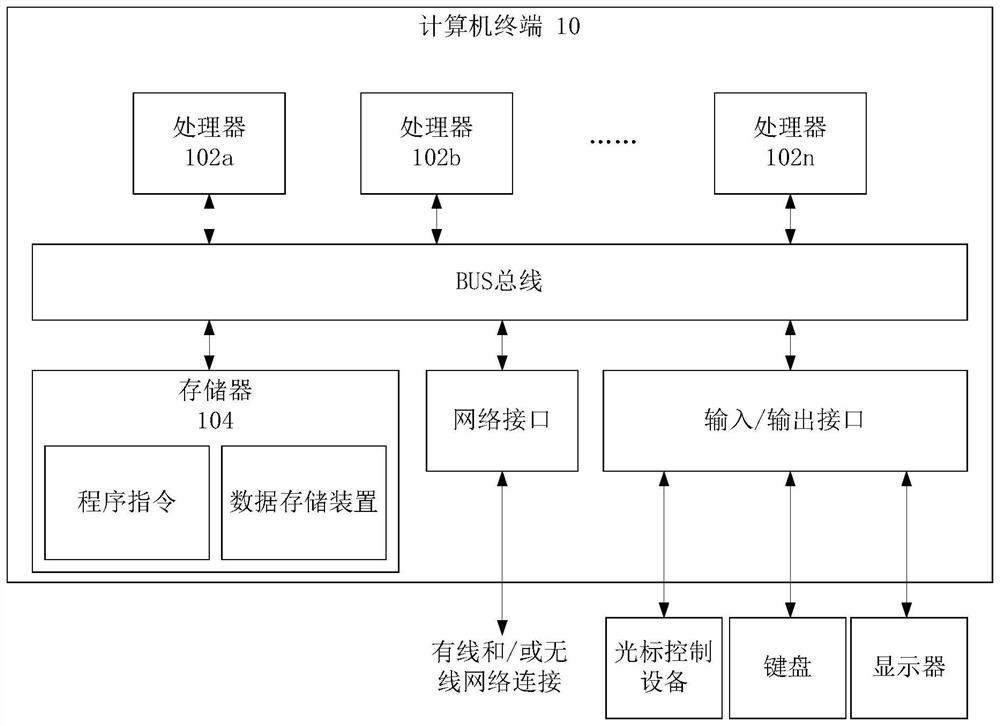
[0031] The embodiment of the fault diagnosis method provided in the embodiment of the present application may be executed in a mobile terminal, a computer terminal or a similar computing device. figure 1 It shows a block diagram of hardware structure of a computer terminal (or electronic equipment) for realizing the fault diagnosis method. Such as figure 1As shown, the computer terminal 10 (or electronic device 10) may include one or more (shown by 102a, 102b, ..., 102n in the figure) processor 102 (the processor 102 may include but not limited to a microprocessor MCU or a processing device such as a programmable logic device FPGA), a memory 104 for storing data, and a transmission module 106 for communication functions. In addition, it can also include: a display, an input / output interface (I / O interface), a universal serial bus (USB) port (which can be included as one of the ports of the I / O interface), a network interface, a power supply and / or camera. Those of ordinary ...

Embodiment 2

[0089] According to an embodiment of the present application, a device for implementing the above fault diagnosis method is also provided, Figure 8 is a structural block diagram of a fault diagnosis device provided according to an embodiment of the present application, such as Figure 8 As shown, the fault diagnosis device includes: a first acquisition module 302 , an output module 304 , a second acquisition module 306 , a diagnosis module 308 and a determination module 310 , and the fault diagnosis device will be described below.

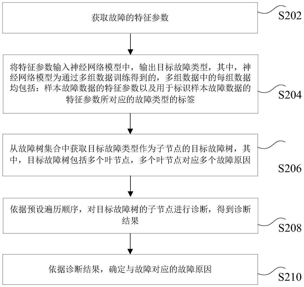
[0090] The first obtaining module 302 is used to obtain the characteristic parameters of the fault;

[0091] The output module 304 is used to input the characteristic parameters into the neural network model, and output the target fault type, wherein the neural network model is obtained through multiple sets of data training, and each set of data in the multiple sets of data includes: the characteristics of the sample fault data Parameters and ta...

Embodiment 3

[0097] Embodiments of the present application may provide an electronic device, and the electronic device may be any computer terminal device in a group of computer terminals.

[0098] Optionally, in this embodiment, the foregoing electronic device may be located in at least one network device among multiple network devices in the computer network.

[0099] Optionally, Figure 9 It is a structural block diagram of an electronic device according to an exemplary embodiment. Such as Figure 9 As shown, the electronic device may include: one or more (only one is shown in the figure) processors 401, and a memory 402 for storing processor-executable instructions; wherein, the processors are configured to execute instructions to achieve the above-mentioned any method of troubleshooting.

[0100] Among them, the memory can be used to store software programs and modules, such as the program instructions / modules corresponding to the fault diagnosis method and device in the embodiment...


PUM


Abstract

The invention provides a fault diagnosis method and device and electronic equipment. The method comprises the following steps: acquiring characteristic parameters of a fault; the feature parameters are input into a neural network model, a target fault type is output, the neural network model is obtained through training of multiple sets of data, and each set of data in the multiple sets of data comprises the feature parameters of the sample fault data and labels used for identifying the fault types corresponding to the feature parameters of the sample fault data; the target fault type is obtained from the fault tree set to serve as a target fault tree of a child node, the target fault tree comprises a plurality of leaf nodes, and the leaf nodes correspond to a plurality of fault causes; according to a preset traversal sequence, the child nodes of the target fault tree are diagnosed, and a diagnosis result is obtained; and determining a fault reason corresponding to the fault according to the diagnosis result. According to the method, the fault tree and the neural network are combined, rapid and accurate positioning of the fault source can be realized, and maintenance personnel can find the fault in time and take precautions against calamity.

Description

technical field [0001] The present invention relates to the field of fault diagnosis, in particular to a fault diagnosis method, its device and electronic equipment. Background technique [0002] With the development of the economy and the continuous expansion of the city scale, high-rise residences, hotels, hotels, office buildings, etc. are constantly increasing, so the number of building electromechanical equipment is also increasing. Among them, the total number of elevators in the country has reached 5.6 million. [0003] While the use of building electromechanical equipment brings convenience to people entering and exiting high-rise buildings, the problems of operation, maintenance and safety of building electromechanical equipment are becoming more and more prominent. However, the number of construction mechanical and electrical equipment technicians has not increased correspondingly. The domestic construction mechanical and electrical equipment industry is facing the...

Claims


Application Information

Patent Timeline
Patent Type & Authority Applications(China)
IPC IPC(8): G06F30/27G06N3/04G06N3/08G06F119/02G06F119/04
Inventor 张海超李璟张倍先马冬梅李然石方
Owner 北京智能建筑科技有限公司
Why Eureka
Try Eureka