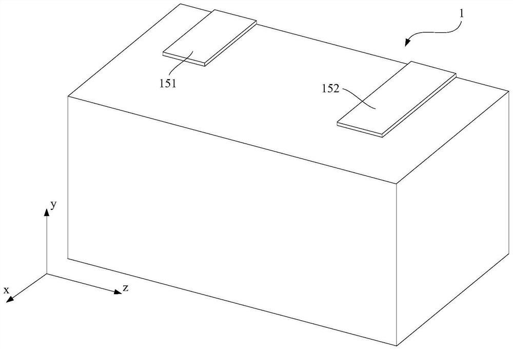
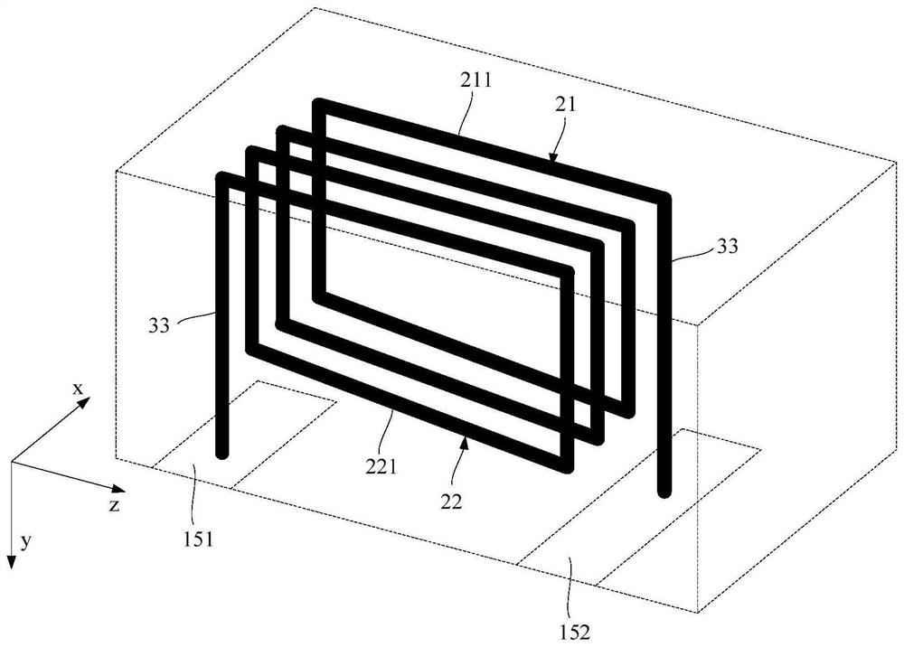
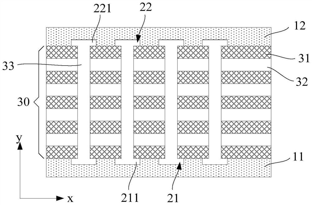
Electromagnetic element and electronic equipment

A technology of electromagnetic components and electronic equipment, applied in electrical components, circuits, magnetic cores/yokes, etc., can solve the problems of low magnetic permeability of magnetic cores, and achieve the effect of improving magnetic permeability and realizing refined production.

Pending Publication Date: 2022-04-12
SHENZHEN SUNLORD ELECTRONICS
View PDF4 Cites 0 Cited by
  • Summary
  • Abstract
  • Description
  • Claims
  • Application Information

AI Technical Summary

Problems solved by technology

However, at present, the magnetic cores of electromagnetic components are generally laminated sintered or thermoset-formed alloy cores. The magnetic permeability of laminated-sintered alloy cores is usually only about 100H / m (Henries / meter), and thermoset-formed The magnetic permeability of the alloy magnetic core is usually only about 40H / m, it can be seen that the magnetic permeability of the existing magnetic core is relatively low

Method used


Image

  • Electromagnetic element and electronic equipment
  • Electromagnetic element and electronic equipment
  • Electromagnetic element and electronic equipment

Examples


Embodiment Construction

[0026] In order to make the purpose, technical solution and advantages of the present application clearer, the technical solution of the present application will be clearly described below in conjunction with specific embodiments and corresponding drawings. Apparently, the embodiments described below are only some of the embodiments of the present application, but not all of them. In the case of no conflict, the following embodiments and technical features thereof can be combined with each other, and also belong to the technical solution of the present application.

[0027] It should be understood that in the description of the embodiments of the present application, the terms "center", "longitudinal", "transverse", "length", "width", "thickness", "upper", "lower", "front", " Orientation indicated by rear, left, right, vertical, horizontal, top, bottom, inside, outside, clockwise, counterclockwise, etc. The positional relationship is based on the orientation or positional rel...


PUM

PropertyMeasurementUnit
thicknessaaaaaaaaaa
thicknessaaaaaaaaaa
magnetic permeabilityaaaaaaaaaa

Abstract

The invention discloses an electromagnetic element and electronic equipment. The electromagnetic element comprises a first electrode layer and a second electrode layer. The dielectric layer and the magnetic layer are sequentially and alternately arranged between the first electrode layer and the second electrode layer in the second direction; each magnetic layer is provided with a groove; the dielectric layer extends and is filled in the groove, and a first hole and a second hole which are opposite to each other are formed in the groove; the first hole and the second hole are insulated from the magnetic layer, and conductive columns are arranged in the first hole and the second hole; the conductive column in the first hole is connected with one end of the first electrode layer and one end of the second electrode layer, the conductive column in the second hole is connected with the other end of the first electrode layer and the other end of the second electrode layer to form a spiral coil, the central axis of the spiral coil is located in the first direction, and the first direction is perpendicular to the second direction. According to the invention, the magnetic conductivity of the electromagnetic element can be improved, and miniaturization and thinning design can be realized.

Description

technical field [0001] The present application relates to the field of electromagnetic induction, in particular to an electromagnetic element and electronic equipment. Background technique [0002] As the size of various electronic devices in the market becomes thinner or more functions, the use of electromagnetic components increases sharply, which requires the continuous miniaturization and thinning of electromagnetic components, especially power devices need to be miniaturized and inductance Under the same premise, the DCR (DC resistance) is further reduced to reduce the heat loss of the device in the circuit. One of the effective ways to reduce the DCR is to increase the magnetic permeability. However, at present, the magnetic cores of electromagnetic components are generally laminated sintered or thermoset-formed alloy cores. The magnetic permeability of laminated-sintered alloy cores is usually only about 100H / m (Henries / meter), and thermoset-formed The magnetic perme...

Claims


Application Information

Patent Timeline
Patent Type & Authority Applications(China)
IPC IPC(8): H01F3/00H01F27/30H01F27/28
Inventor 余瑞麟郭海戴春雷毛海波
Owner SHENZHEN SUNLORD ELECTRONICS
Why Eureka
Try Eureka