433 remote control system and receiving method
A technology of remote control and receiving method, applied in the field of remote control starting devices, can solve the problems of pairing failure, 433 remote control not accepting data frames, unable to store multiple data frames and restore deleted data frames, etc., to improve the success rate. Effect
- Summary
- Abstract
- Description
- Claims
- Application Information
AI Technical Summary
Problems solved by technology
Method used
Image
Examples
Embodiment 1
[0036] In this embodiment, a 433 remote control receiving method, the method steps include:
[0037] S1. The system starts up. When the user needs to perform pairing, the user uses the pairing function, and the device starts to emit 433 signal waves and receive external signal waves;
[0038] S2. The signal receiver receives the external 433 Hz signal wave, and the signal receiver will receive the signal wave of the 433 Hz channel through the receiving antenna;
[0039] S3. The signal receiver receives the paired signal wave, and the signal light starts to flash, indicating that the device starts to pair;
[0040] S4, the signal interceptor begins to discard and shield the received start frame, and only accepts the data frame behind the start frame;
[0041] S5. The signal light stops flashing, the data transmission is completed, and the pairing is successful;
[0042] S6. The data frame of successful pairing is stored in the memory chip, so that it is convenient to search d...
Embodiment 2
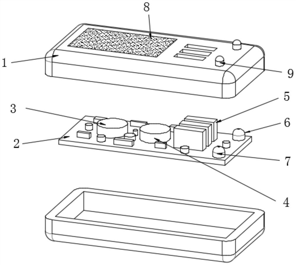
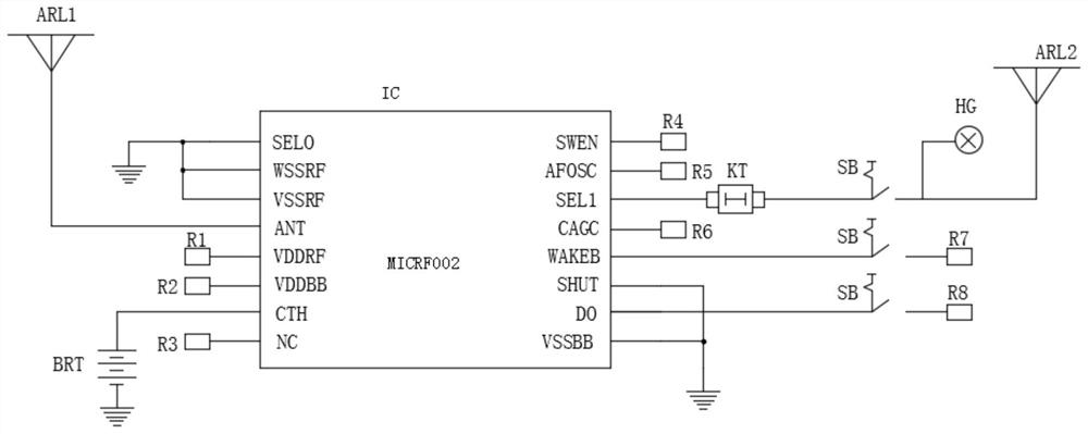
[0048] A 433 remote control system and receiving method of this embodiment, such as figure 1 and 3 As shown, it includes a controller 1, a circuit board 2 is fixedly installed in the inner cavity of the controller 1, a battery 3 is fixedly installed on the top of the circuit board 2, and a control chip 4 is fixedly installed on the top of the circuit board 2 and to the right of the battery 3 , the top of the circuit board 2 and the right side of the control chip 4 are fixedly installed with the control button 5, the top of the circuit board 2 and the right side of the control button 5 is fixedly installed with the signal transmitter 6, and the top of the circuit board 2 is located at the signal The front of the transmitter 6 is fixedly equipped with a signal receiver 7, the top of the control button 5 runs through the controller 1 and extends to the outside of the controller 1, the top of the controller 1 is fixedly installed with a control panel 8, and the input terminal of t...
Embodiment 3
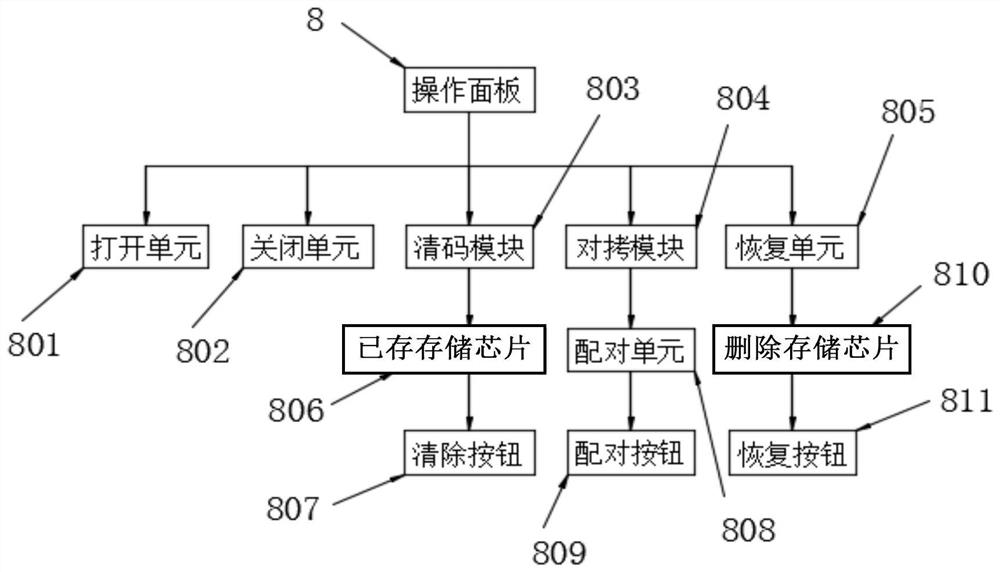
[0051] Such as figure 1 and 2 As shown, the output end of the control panel 8 is connected with the opening unit 801, and the output end of the control panel 8 is connected with the closing unit 802. The control panel 8 is composed of a liquid crystal display and can control the program inside the control chip 4.
[0052] Such as figure 1 and 2 As shown, the output end of the control panel 8 is connected to the clearing module 803 , and the output end of the control panel 8 is connected to the copying module 804 .
[0053] Such as figure 1 and 2 As shown, the output end of the control panel 8 is connected to the recovery unit 805, and the output end of the clearing module 803 is connected to the stored memory chip 806. The stored memory chip 806 stores the data frames that are also successfully paired, and is taken by the user. Name, you can pair it directly when you need to use it next time and search for pairing again wirelessly.
[0054] Such as figure 1 and 2 As sh...
PUM
 Abstract
Description
Claims
Application Information
 - R&D
- Intellectual Property
- Life Sciences
- Materials
- Tech Scout
- Unparalleled Data Quality
- Higher Quality Content
- 60% Fewer Hallucinations
Browse by: Latest US Patents, China's latest patents, Technical Efficacy Thesaurus, Application Domain, Technology Topic, Popular Technical Reports.
© 2025 PatSnap. All rights reserved.Legal|Privacy policy|Modern Slavery Act Transparency Statement|Sitemap|About US| Contact US: help@patsnap.com


