Supercharge Your Innovation With Domain-Expert AI Agents!

Dispersion machine for processing graphene modified PTC (Positive Temperature Coefficient) thermosensitive conductive ink

A graphene modified, conductive ink technology, applied in mixers, mixer accessories, mixers with rotary stirring devices, etc., can solve problems such as splashing, inability to clean and scrape ink, and ink easily splashing, and increase sealing. sexual effect

Pending Publication Date: 2022-04-15
江苏宥拓新材料有限公司
View PDF1 Cites 0 Cited by
  • Summary
  • Abstract
  • Description
  • Claims
  • Application Information

AI Technical Summary

Problems solved by technology

[0004] Because the ink is liquid and has strong fluidity, when the dispersing device processes the ink, part of the ink is prone to splash, and then splashes to the upper end of the dispersing charging tank, which makes the ink device unable to use centrifugal force during processing. The ink on the top of the barrel is cleaned and scraped

Method used


Image

  • Dispersion machine for processing graphene modified PTC (Positive Temperature Coefficient) thermosensitive conductive ink
  • Dispersion machine for processing graphene modified PTC (Positive Temperature Coefficient) thermosensitive conductive ink
  • Dispersion machine for processing graphene modified PTC (Positive Temperature Coefficient) thermosensitive conductive ink

Examples


Embodiment 1

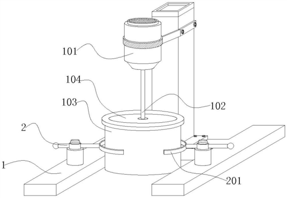
[0031] Embodiment 1: a kind of dispersing machine for processing of graphene modified PTC thermosensitive conductive ink, comprises device main body 1, and the upper end of device main body 1 is equipped with motor 101, and the lower end of motor 101 is rotated with stirring support 102, and the lower end of device main body 1 A material barrel 103 is installed, and the upper end of the material barrel 103 is movably nested and connected with a cover plate 104. Both sides of the device main body 1 are provided with a limiting mechanism that can quickly clamp both sides of the material barrel 103, and the inside of the material barrel 103 is provided with A transmission mechanism that can automatically scrape the upper end of the cover plate 104;

[0032] Wherein: the inside of the cover plate 104 runs through a hole, the two sides of the hole are provided with grooves, the motor 101 is electrically connected to the power supply through the power cord, the stirring support 102 r...

Embodiment 2

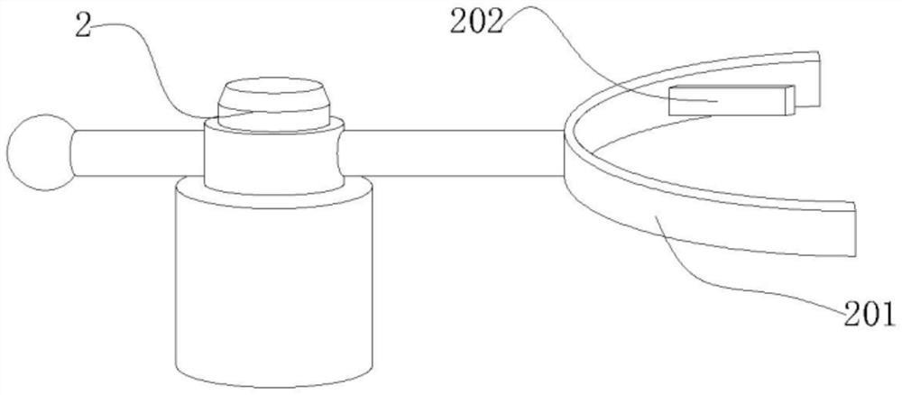
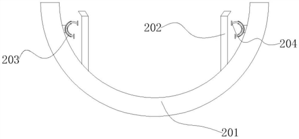
[0033] Embodiment 2: with reference to instruction manual figure 1 , 2 , 3 and 5, it can be seen that the difference between embodiment 2 and embodiment 1 is that the limiting mechanism includes a clamping frame 2, a clamping ring 201, a swash plate 202, a collar 203, a limiting ring 204 and a roller 3, the clamping The holder 2 is installed on both sides of the lower end of the device main body 1, the clamping ring 201 slides on one side of the clamping frame 2, the swash plate 202 is embedded on both sides of the clamping ring 201, and the collar 203 is installed on the clamping ring 201 close to On both sides of the swash plate 202 , the limit ring 204 slides through the outer side of the sleeve 203 , and the roller 3 rotates on both sides inside the cover plate 104 ;

[0034] Wherein: the clamping frame 2, the clamping frame 2 is arranged on both sides of the material barrel 103, and the clamping frame 2 is convenient for the clamping ring 201 to limit the both sides of t...

Embodiment 3

[0042] Embodiment 3: with reference to instruction manual Figure 4-8 It can be seen that the difference between Embodiment 3 and Embodiments 1 and 2 is that the transmission mechanism includes gear 4, gear piece 401, rotating frame 5, snap ring 501, block 502, scraper 503, track 504 and air bag 505, and the gear 4 Rotate on the outside of the stirring bracket 102, the tooth piece 401 is embedded on the outside of the gear 4, the block 502 is rotated and fitted on the outside of the tooth piece 401, the snap ring 501 is installed on one side of the block 502, and the rotating frame 5 rotates on the block On one side of the ring 501, the scraper 503 slides on the upper end of the rotating frame 5, the track 504 is arranged above the inside of the rotating frame 5, and the airbag 505 is stretched on both sides of the rotating frame 5;

[0043] Wherein: gear 4, the two ends of gear 4 are inclined 25-45 ° and are set, and the inclined setting of gear 4 can avoid the ink from accum...


PUM


Abstract

The invention provides a dispersion machine for processing graphene modified PTC thermosensitive conductive ink, which comprises a device main body, a motor is mounted at the upper end of the device main body, a stirring bracket is rotatably arranged at the lower end of the motor, a material barrel is mounted at the lower end of the device main body, and a cover plate is movably nested and connected to the upper end of the material barrel; limiting mechanisms capable of rapidly clamping the two sides of a material barrel are arranged on the two sides of the device body, a transmission mechanism capable of automatically cleaning and scraping the upper end of a cover plate is arranged in the material barrel, a clamping frame is manually made to horizontally slide, the clamping frame drives a clamping ring to limit the two sides of the material barrel, an inclined plate on the inner side of the clamping ring is extruded by the material barrel, the inclined plate swings in an inclined mode, and the material barrel is clamped by the clamping ring. When the inclined plate swings, the inclined plate extrudes one end of the limiting ring, the limiting ring slides in the lantern ring, the limiting ring is arranged in a bent semi-arc shape, at the moment, the other end of the limiting ring can extrude the side face of the inclined plate to form relative extrusion on the inclined plate, the inclined plate can form limiting extrusion on the material barrel, and the effect of rapidly limiting the material barrel is achieved.

Description

technical field [0001] The invention relates to the technical field of ink processing, in particular to a dispersing machine for graphene-modified PTC heat-sensitive conductive ink processing. Background technique [0002] When graphene is processed, it is necessary to stir and disperse the ink. Usually, a disperser is used, and the disperser is widely used in high-efficiency equipment for stirring, dispersing and dissolving coatings and solids. The technical inspiration for the disperser; [0003] At present, CN202111018226.0 in the prior art is an energy-recoverable offset printing ink production dispersion device and its use method, which discloses an energy recovery offset printing ink production dispersion device and its use method. During the process of dispersion, the particles produced by the dispersion pose a threat to the health of the staff. During the dispersion process of the offset printing ink, the discharge mechanism is automatically driven by the airflow to ...

Claims


Application Information

Patent Timeline
Patent Type & Authority Applications(China)
IPC IPC(8): B01F27/90B01F27/091B01F35/12B01F35/31B01F35/40B01F101/35
Inventor 史宇正
Owner 江苏宥拓新材料有限公司
Features
  • R&D
  • Intellectual Property
  • Life Sciences
  • Materials
  • Tech Scout
  • Unparalleled Data Quality
  • Higher Quality Content
  • 60% Fewer Hallucinations
Learn More