Construction structure and construction method for shield tunneling machine to penetrate through existing shield tunnel in close range

A technology for shield tunnels and existing tunnels, which is applied to tunnels, earthwork drilling, mining equipment, etc., and can solve the problem of difficulty in achieving uniform grouting across the entire section, the limited number of grouting holes reserved for pipe rings, and increasing the size of existing tunnels. Problems such as floating and deformation of the tunnel can save manpower and machine investment, reduce soil disturbance, and avoid hard contact

Pending Publication Date: 2022-04-15
南京工大交通科学研究院(滁州)有限公司
View PDF0 Cites 1 Cited by
  • Summary
  • Abstract
  • Description
  • Claims
  • Application Information

AI Technical Summary

Problems solved by technology

In fact, the number of grouting holes reserved for the pipe ring is limited, and it is difficult to achieve uniform grouting across the entire section, resulting in unsatisfactory construction quality; There is a problem of insufficient construction space
Relevant studies have shown that the bolts that have not penetrated into the bedrock have no anti-floating effect under the condition of a large amount of unloading of the soil above the tunnel. Instead, the tensile force will be transmitted to the deep soil to destroy its integrity, and then increase the floating deformation of the existing tunnel.

Method used


Image

  • Construction structure and construction method for shield tunneling machine to penetrate through existing shield tunnel in close range
  • Construction structure and construction method for shield tunneling machine to penetrate through existing shield tunnel in close range
  • Construction structure and construction method for shield tunneling machine to penetrate through existing shield tunnel in close range

Examples


Embodiment 1

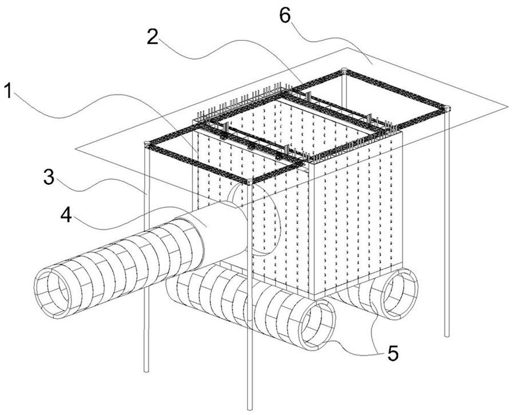
[0053] A construction structure for a shield tunnel passing through an existing shield tunnel at a short distance, including an anti-floating well 1, a ground beam system 2, a pile foundation 3 and other components. Such as figure 1 As shown, the existing shield tunnel 5 located underground extends horizontally, and the newly constructed shield tunnel needs to pass above the existing shield tunnel 5 and extend longitudinally.

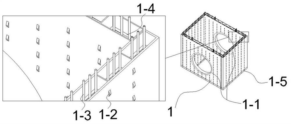
[0054] The anti-floating-sinking well 1 is a sub-compartment steel caisson structure, and the interior can be filled with concrete as required to ensure that the weight of the anti-floating-sinking well is basically the same as that of the replaced soil. Gas niches 1-2 are arranged on the outer panels of each warehouse of the anti-floating and sinking well 1. The gas niches 1-2 are in the form adopted by conventional caissons, and the arrangement of high-pressure gas pipelines used in conjunction with the gas niches 1-2 is no longer shown in the figure....

Embodiment 2

[0065] In this embodiment, the construction of anti-floating and sinking well 1 is the same as the conventional air curtain caisson method. Since the air curtain method sinking generally meets the construction requirements, the mud suction pipe can be used as a supplementary measure.

[0066] On the basis of Embodiment 1, the present embodiment installs a multifunctional blade foot structure 1-5 at the bottom of the anti-floating well 1, and the multifunctional blade foot structure 1-5 consists of multiple blade feet, rubber blocks and multiple Working tube 1-3 is composed.

[0067] The plurality of blade feet include a first blade foot 1-5-1 and a second blade foot, and the first blade foot 1-5-1 and the second blade foot are each provided with a frustum-shaped concave cavity with an opening downward , the frustum-shaped concave cavity is wide at the bottom and narrow at the top, and is a concave cavity that gradually expands downward. The top plate of the concave cavity is ...

Embodiment 3

[0080] In the case of poor geological conditions, it is expected that the shield machine 4 will generate a large disturbance after tunneling.

[0081] Therefore, on the basis of the second embodiment, this embodiment adds a working tube for grouting. The grouting pipe is connected to the second blade foot, and after the anti-floating and sinking well 1 is in place, the grouting pipe is used for grouting to form an improved soil mass under the caisson. The stiffness and strength of the improved soil are improved, and the integrity is stronger, and better anti-floating effect can be obtained after the tunneling of the shield machine 4 passes.

[0082] The grouting pipe can be installed separately, or can be made into a composite pipe with the dredge pipe, sharing the main conveying pipeline, so as to simplify the construction process and reduce the construction cost.


PUM


Abstract

The invention provides a construction structure and a construction method for a shield to penetrate through an existing shield tunnel in a close range, the construction structure comprises an anti-floating sinking well, a ground cross beam system and a pile foundation, the ground cross beam system comprises a steel truss girder, a working platform and a forced downward pressing device, and the pile foundation comprises pile bodies driven below four corner points of the steel truss girder. And four corner points of the steel truss girder are connected with pile heads, higher than the ground, of the pile bodies. The working platforms are installed on the two sides of the top of the anti-floating sinking well so as to arrange the forced pressing devices, the ground cross beam system is installed on the periphery of the top of the anti-floating sinking well, the ground cross beam system is connected with the pile foundations on the periphery of the anti-floating sinking well, anti-floating reinforcement of the existing tunnel can be achieved, and too large disturbance of construction of a newly-built tunnel to the existing tunnel is avoided. The air niche in the form of an air curtain is arranged on the well wall of the anti-floating sinking well, and is further matched with the blade feet and the working pipes in various forms, so that the sinking posture and speed of the sinking well can be controlled, the sinking well sinks with small soil disturbance and is finally attached to the top of the existing tunnel, and the purpose of controlling floating of the existing tunnel is achieved.

Description

technical field [0001] The invention belongs to the technical field of construction engineering, and in particular relates to a construction structure and a construction method of a shield tunnel passing through an existing shield tunnel at a short distance. Background technique [0002] With the rapid development of underground transportation in my country, shield construction has been widely used in underground projects due to its high efficiency, safety, and low environmental impact. The construction conditions of shield tunnels close to existing tunnels are becoming more and more common. Generally speaking, shield tunneling will cause the existing tunnel to float up and cause problems such as the development of cracks between segments, failure of waterproofing between segments, and excessive changes in the longitudinal curvature radius of the tunnel. It should be pointed out that in order to meet the needs of urban traffic flow in municipal tunnels, the application of la...

Claims


Application Information

Patent Timeline
Patent Type & Authority Applications(China)
IPC IPC(8): E21D9/00E21D9/06E21D9/14
Inventor 朱利明杨书一王霆陈燕平
Owner 南京工大交通科学研究院(滁州)有限公司
Why Eureka
Try Eureka