Pressure vessel and manufacturing method thereof

A technology for pressure vessels and pressure tanks, applied in the field of pressure vessels, can solve problems such as poor sealing effect, reduced usability, and potential safety hazards, and achieve the effects of good stability, improved performance, and less leakage

Pending Publication Date: 2022-04-15
HUAIAN DUOLE THERMAL EQUIP CO LTD
View PDF6 Cites 1 Cited by
  • Summary
  • Abstract
  • Description
  • Claims
  • Application Information

AI Technical Summary

Problems solved by technology
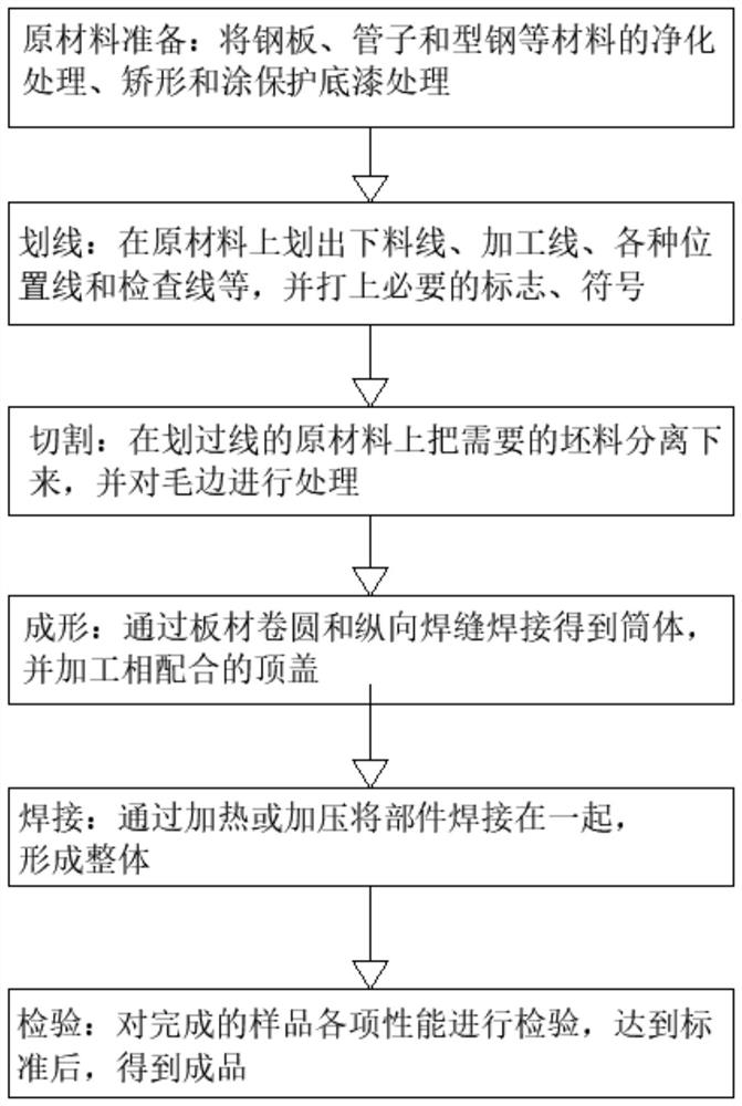
[0004] In order to solve the above technical problems, the present invention provides a pressure vessel and its manufacturing method, which solves the problem that the structure of the existing pressure vessel is too simple, and the tank body and the tank cover are easily affected by vibration or external force, thereby causing looseness. The sealing effect is poor, and the toxic and harmful substances inside the cavity leak, which poses a large safety hazard and reduces the problem of usability

Method used


Image

  • Pressure vessel and manufacturing method thereof
  • Pressure vessel and manufacturing method thereof
  • Pressure vessel and manufacturing method thereof

Examples


Embodiment 1

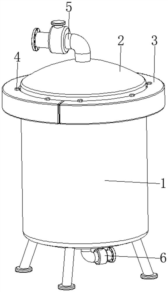
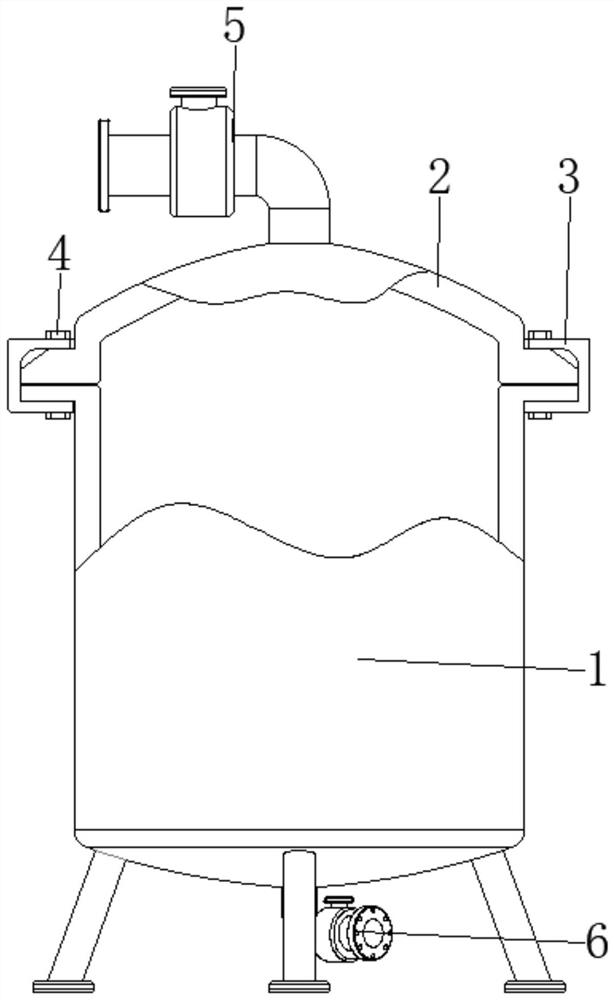
[0037] see Figure 1-7 , the present invention provides a technical solution: a pressure vessel, including a pressure tank body 1, a tank cover device 2, a pressing device 3, and a locking bolt 4. The tank cover device 2 is arranged on the top of the pressure tank body 1, and the pressing The device 3 is arranged at the position where the surface edge of the tank cover device 2 corresponds to the top edge of the pressure tank body 1, and the top surface of the pressure tank body 1, the surface edge of the tank cover device 2 and the clamping device 3 are all connected by locking bolts 4 fixed connection;

[0038] A material inlet 5 is provided at the center of the top of the cover device 21 , and a material outlet 6 is provided at the center of the bottom of the pressure tank body 1 .

[0039] The top of the surface of the pressure tank body 1 and the edge of the surface of the tank cover device 2 are provided with threaded holes matching the locking bolts 4, and the surface ...

Embodiment 2

[0041] The tank cover device 2 is provided with a cover shell device 21, an arc-shaped elastic member 22, an arc-shaped bead 23, an elastic bag strip 24, and a stabilizing device 25. The cover shell device 21 is arranged on the top of the pressure tank body 1, and the arc-shaped elastic member 22 The bottom end is fixed on the bottom edge of the surface of the cover device 21 and is close to the edge, the bottom edge of the arc-shaped bead 23 is fixedly connected with the top of the arc-shaped elastic member 22, and the elastic bag strip 24 is arranged on the surface of the cover device 21 and the arc-shaped bead 23 Between the corresponding two sides of the bottom and close to the arc-shaped elastic member 22, the stabilizing device 25 is arranged on the surface edge of the cover device 21 and close to the position of the elastic bag strip 24, and is clamped by the clamping device 3 and combined with The locking of the locking bolt 4 causes the clamping pressure to be applied ...

Embodiment 3

[0046] The clamping device 3 is provided with an arc-shaped clamping base 31, a notch clamping groove 32, and a limit groove 33. The arc-shaped clamping base 31 is arranged at a position corresponding to the edge of the surface of the cover device 21 and the top of the surface of the pressure tank body 1. The notch The card slot 32 is set inside the arc-shaped pressing base 31 and is located on one side of the surface. The inner surface of the inner surface is opened with a notch slot 32, and then the position corresponding to the top edge of the surface of the pressure tank body 1 and the surface edge of the cover body 211 can be clamped, and the stabilizing device 25 is used to cooperate with the limiting groove 33, and then the cover shell The main body 211 is positioned so that the space between the pressure tank body 1 and the cover shell main body 211 is not easy to move arbitrarily, and the influence of vibration is reduced.


PUM


Abstract

The invention discloses a pressure container and a manufacturing method thereof.The pressure container comprises a pressure tank body, a tank cover device, a clamping and pressing device and a locking bolt, and the clamping and pressing device is arranged at the position, corresponding to the edge of the top of the surface of the pressure tank body, of the edge of the surface of the tank cover device; the top of the surface of the pressure tank body, the edge of the surface of the tank cover device and the clamping and pressing device are fixedly connected through locking bolts, the edge of the bottom of the arc-shaped pressing strip is fixedly connected with the top end of the arc-shaped elastic piece, and the elastic bag strip is arranged between the two sides, corresponding to the bottom of the arc-shaped pressing strip, of the surface of the cover shell device and is close to the arc-shaped elastic piece. The stabilizing device is arranged at the position, close to the elastic bag strip, of the edge of the surface of the cover shell device. According to the pressure container and the manufacturing method thereof, the shockproof protection effect is achieved, the tank body and the tank cover can be firmly connected, the influence of vibration or external force is reduced, looseness is not prone to occurring, sealing is facilitated, leakage is not prone to occurring, safety and reliability are achieved, and the use performance is improved.

Description

technical field [0001] The invention relates to the technical field of pressure vessels, in particular to a pressure vessel and a manufacturing method thereof. Background technique [0002] A pressure vessel refers to a closed device that holds gas or liquid and carries a certain pressure. The pressure vessel has a wide range of uses. It has an important position and role in many sectors such as industry, civil, military, and many fields of scientific research. The most widely used in chemical industry and petrochemical industry, pressure vessels are mainly used for heat transfer, mass transfer, reaction and other processes, as well as storage and transportation of pressurized gas or liquefied gas. [0003] At present, the structure of the existing pressure vessel is too simple, and the tank body and the tank cover are easily affected by vibration or external force, resulting in loosening, making the sealing effect poor, causing the leakage of toxic and harmful substances in...

Claims


Application Information

Patent Timeline
Patent Type & Authority Applications(China)
IPC IPC(8): F16J12/00F16J13/00F16J13/24F17C1/00F17C13/00
CPCF16J12/00F16J13/00F16J13/24F17C1/00F17C13/00F17C2270/05
Inventor 庄海军
Owner HUAIAN DUOLE THERMAL EQUIP CO LTD
Why Eureka
Try Eureka