Low-scattering carrier for airfoil front edge wave-absorbing structure RCS test and test method

A technology of wave structure and low scattering, applied in the field of electromagnetic scattering measurement, can solve the problems of difficulty in using low-scattering carriers, shorten the manufacturing cost and cycle, etc., and achieve the effect of eliminating chaotic scattering and reducing the peak value of specular scattering.

Active Publication Date: 2022-04-15
CHENGDU AIRCRAFT INDUSTRY GROUP
View PDF23 Cites 2 Cited by
  • Summary
  • Abstract
  • Description
  • Claims
  • Application Information

AI Technical Summary

Problems solved by technology

Also, due to the limitation of its flat shape, it is difficult to be used as a low-scattering carrier for the RCS test of the slender airfoil leading edge absorbing structure
[0006] Chinese Patent Publication No. CN 111504952 B, published on August 7, 2020, the name of the invention is a low-scattering carrier that takes into account both horizontal and vertical polarization and its testing method. Low-scattering carrier and its test method. The carrier disclosed in this application is in the shape of a diamond whose rear end is upturned. Its advantage is that the test of two polarizations can be completed by using a set of carriers. It is designed for the stealth test of antennas and exposed objects. It is flat and diamond-shaped, and it is difficult to be used as a low-scattering carrier for the RCS test of the slender airfoil leading edge absorbing structure.
[0007] Chinese Patent Publication No. CN 112834997 A, published on May 25, 2021, the name of the invention is a method for designing the shape of a low-scattering carrier with a rectangular opening feature, and the application discloses a low-scattering carrier with a rectangular opening feature The shape design method has the advantage of adopting a simple shape and surface to construct a low-scattering carrier shape, which is easy to process and manufacture, and shortens the manufacturing cost and cycle. The disadvantage is that the shape of the carrier restricts it to the RCS of an aeroengine equipped with a rectangular nozzle. It is difficult to be used as a low-scattering carrier for the RCS test of the slender airfoil leading edge absorbing structure

Method used


Image

  • Low-scattering carrier for airfoil front edge wave-absorbing structure RCS test and test method
  • Low-scattering carrier for airfoil front edge wave-absorbing structure RCS test and test method
  • Low-scattering carrier for airfoil front edge wave-absorbing structure RCS test and test method

Examples


Embodiment 1

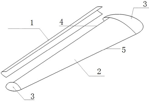
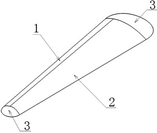
[0046] This embodiment proposes a low-scattering carrier for the RCS test of the leading edge wave-absorbing structure of the airfoil, which is used for the RCS test of the wave-absorbing structure of the airfoil leading edge; figure 2 , image 3 , Figure 4 , Figure 5 As shown, the low-scattering carrier includes a front edge cover plate 1 and a carrier body 2;

[0047] The carrier body 2 is a horizontally arranged flat strip-shaped structure, and the strip-shaped structure of the carrier body 2 is a metal hollow structure with a thick middle of the outer structure and gradually flattened front and rear sides; the thickness direction of the carrier body 2 The section above is in the shape of a water drop with a blunt front and a sharp rear;

[0048] The front edge 4 of the elongated structure of the carrier body 2 is a linear structure that is attached to the front edge wave-absorbing structure of the airfoil, and the curved surface at the junction of the front edge cove...

Embodiment 2

[0053] This embodiment is based on the above-mentioned embodiment 1, in order to better realize the present invention, further, as figure 2 , image 3 As shown, the low-scattering carrier also includes a carrier end face 3; the carrier end face 3 is a flat cover structure in which the upper and lower curved surfaces shrink into a curve; the carrier end face 3 is provided with one large and one small two, respectively. The large and small ends of the flat elongated structure disposed on the carrier main body 2 are detachably corresponding to form a structure that can fix the front edge cover plate 1 on the carrier main body 2 .

[0054] Further, the width of the narrower end of the carrier body 2 is greater than or equal to 3.2 times the signal wavelength corresponding to the lowest frequency tested during the RCS test.

[0055] Further, the length of the low-scattering carrier is smaller than the size of the quiet zone of the test site when the RCS test is performed.

[005...

Embodiment 3

[0060] In this embodiment, on the basis of any one of the above-mentioned embodiments 1-2, the setting principle of each component is further described:

[0061] Such as figure 2 , image 3 As shown, the carrier adopts a metal hollow structure to reduce weight, and the surface roughness is Ra≤1.6. It is composed of a front edge cover plate 1, a carrier body 2, and a carrier end surface 3. The head, and the opposite side is the rear. The shape of the leading edge cover plate 1 is the same as that of the leading edge wave-absorbing structure of the airfoil. Its function is to be installed on the main body of the carrier for testing the RCS of the all-metal carrier. It can be disassembled, and the wave-absorbing structure at the leading edge of the airfoil is installed in situ. The upper and lower curved surfaces of the carrier end surface 3 shrink into a curve, forming a flat shape. The edge diffraction of the curve is used to replace the specular scattering brought by the pla...


PUM


Abstract

The invention provides a low-scattering carrier for RCS (radar cross section) test of an airfoil front edge wave-absorbing structure and a test method, and firstly provides the low-scattering carrier which can be used for the RCS test of the airfoil front edge wave-absorbing structure due to the special structure, and the test method provided based on the low-scattering carrier can be directly applied to the low-scattering carrier, so that the test efficiency is improved. The problem that an existing low-scattering carrier is difficult to apply to an airfoil front edge wave-absorbing structure RCS test is solved.

Description

technical field [0001] The invention belongs to the field of electromagnetic scattering measurement, and in particular relates to a low-scattering carrier and a testing method for RCS testing of an airfoil leading edge wave-absorbing structure. Background technique [0002] The specular scattering at the leading edge of the aircraft wing and tail is one of the important forward scattering sources of the aircraft. One way to deal with it is to design the leading edge sweep angle of the wing and tail to be greater than 45° to Offset the leading edge specular echo to the forward ±45° sector, but this measure will bring adverse effects, such as for the wing, the excessive sweep angle will reduce the lift line slope of the wing And the maximum lift coefficient, even the phenomenon of "pitch up" will appear, causing the aircraft to lose control. Therefore, the leading edge sweep angle of the general fighter wing is between 35° and 45°. For example, the leading edge sweep angle of ...

Claims


Application Information

Patent Timeline
Patent Type & Authority Applications(China)
IPC IPC(8): G01S7/41B64F5/60
CPCY02T90/00
Inventor 梁爽杨桔任杰方雄邹宁聂暾王宇恒
Owner CHENGDU AIRCRAFT INDUSTRY GROUP
Why Eureka
Try Eureka