Isolation sleeve

A technology of isolating sleeves and sleeve holes, applied in the direction of insulators, contact surface shape/structure, etc., can solve problems such as insufficient electrical insulation performance, difficulty in centering moving contacts and static contacts, etc., and achieve good voltage equalization effect, Conducive to the effect of uniform distribution and uniform wall thickness

Pending Publication Date: 2022-04-15
PINGGAO GRP
View PDF1 Cites 0 Cited by
  • Summary
  • Abstract
  • Description
  • Claims
  • Application Information

AI Technical Summary

Problems solved by technology

[0004] The purpose of the present invention is to provide a spacer sleeve to solve the technical problems in the prior art that the centering is difficult when the moving contact and the static contact are plugged together, and the electrical insulation performance is insufficient.

Method used


Image

  • Isolation sleeve
  • Isolation sleeve
  • Isolation sleeve

Examples


Embodiment 1

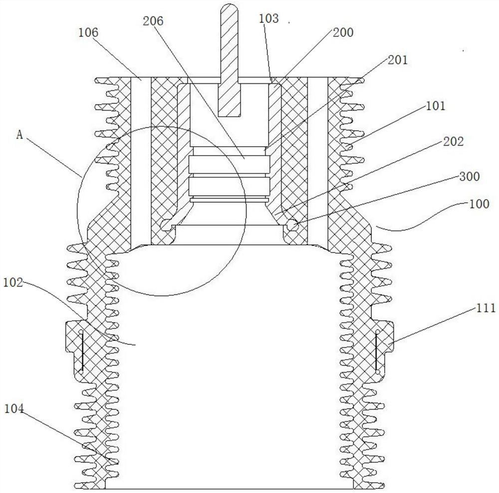
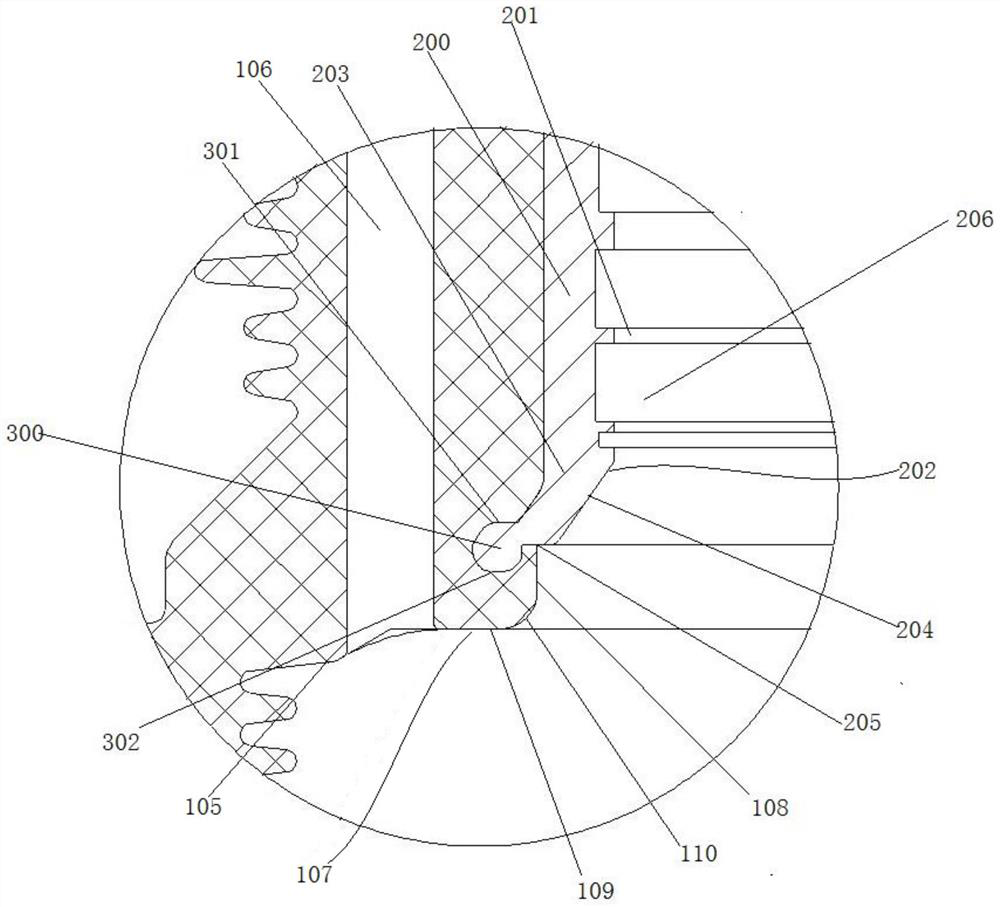
[0044] Such as Figure 1 to Figure 5 As shown, the present embodiment provides an isolating bushing. The isolating bushing includes an insulating casing 100 and a static contact 200. The static contact 200 is arranged in the casing hole 101 of the insulating casing 100. The lower end of the static contact 200 has a horn Shaped turning edge 202 and the outer ring 300 connected at the end of turning edge 202, the outer wall surface of turning edge 202 is an outer tapered surface 203, and the inner wall surface of turning edge 202 includes a tapered section 204 and a horizontal section 205, wherein the tapered section 204 Formed by the hole wall of the tapered hole at the bottom of the socket 201, the hole at the lower end of the tapered hole forms the lower end opening of the socket 201, for when the movable contact 400 is inserted into the static contact 200, the movable contact 400 for alignment.

[0045] Specifically, such as figure 1 and figure 2 As shown, the insulating...

Embodiment 2

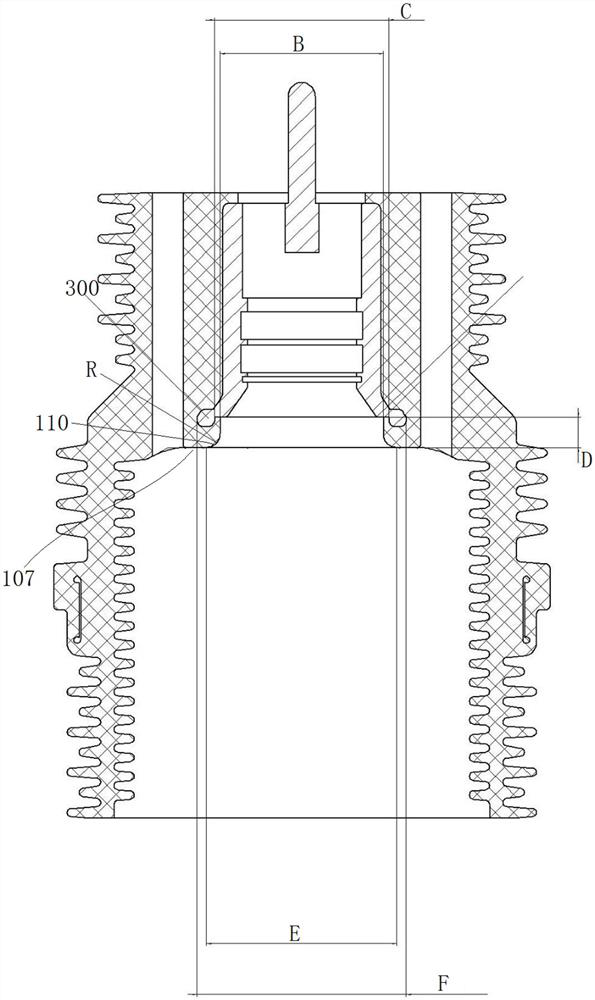
[0053] The difference between this embodiment and Embodiment 1 is that in Embodiment 1, the lower end surface of the outer ring is lower than the horizontal section. However, in this embodiment, the lower end surface of the outer ring is flush with the horizontal section.

Embodiment 3

[0055] The difference between this embodiment and Embodiment 1 lies in that in Embodiment 1, the transition between the wall surface of the hole and the end surface of the hole is rounded. In this embodiment, the wall surface of the hole and the end surface of the orifice are perpendicular to each other, and the transition between the wall surface of the hole and the end surface of the orifice is at right angles.


PUM

PropertyMeasurementUnit
sizeaaaaaaaaaa
thicknessaaaaaaaaaa
sizeaaaaaaaaaa

Abstract

The invention provides an isolating sleeve which comprises an insulating jacket and a static contact, the lower end of the static contact is provided with a trumpet-shaped turned edge and an outer ring connected to the tail end of the turned edge, the outer wall surface of the turned edge is an outer conical surface, and the inner wall surface of the turned edge comprises a conical section and a horizontal section. The horizontal section is connected to the lower end of the conical section and extends in the direction away from the central axis. The lower end face of the outer ring is lower than that of the horizontal section. The hole wall of the upper section of the insulating jacket is provided with an annular wrapping section used for wrapping the outer ring and the turned edge, the horizontal section is flush with the lower end opening and partially extends into the annular wrapping section, the annular wrapping section comprises a hole wall face facing the central axis and a hole opening end face, and the hole opening end face is formed by the central portion of the step face. A set distance is formed between the orifice end face of the annular wrapping section and the lower end face of the horizontal section, so that the annular wrapping section has a set thickness. The isolating sleeve provided by the invention can effectively solve the technical problems that the centering is difficult when the moving contact and the static contact are plugged and the electrical insulation performance of the insulating jacket is insufficient.

Description

technical field [0001] The invention relates to a bushing with a static contact used in a switchgear for power supply and distribution, which is used to cooperate with a busbar and a moving contact to realize circuit switching, in particular to an isolating bushing. Background technique [0002] The isolation sleeve is mainly used for the connection of the internal and external circuits of the cabinet and plays an insulating role on the external cabinet. At present, the structure of the isolation bushing on the market is similar to the bushing assembly structure disclosed in the invention patent with the authorized announcement number CN105262022B. The bushing assembly includes an insulating jacket and a static contact. The wall includes the upper hole wall and the corrugated hole wall below the upper hole wall. There is a downward step surface between the upper hole wall and the corrugated hole wall. The static contact is coaxially embedded and fixed in the upper hole wall ...

Claims


Application Information

Patent Timeline
Patent Type & Authority Applications(China)
IPC IPC(8): H01B17/58H01H1/06
Inventor 卢健唐猛郭锋冯祥伟康博袁端磊李军辉张永辉朱彦卿王海燕朱志豪娄源通翟停停庞建
Owner PINGGAO GRP
Why Eureka
Try Eureka