Liver section blood flow blocking device
A technology of blood flow blocking and sectioning, which is applied in the field of liver surgery tools, can solve problems such as inconvenient operation, and achieve the effect of convenient disassembly and convenient tube insertion work
- Summary
- Abstract
- Description
- Claims
- Application Information
AI Technical Summary
Problems solved by technology
Method used
Image
Examples
Embodiment 1
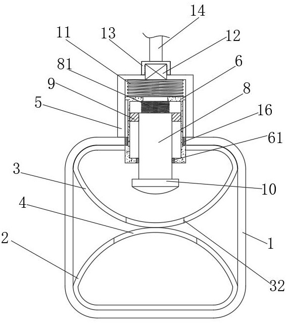
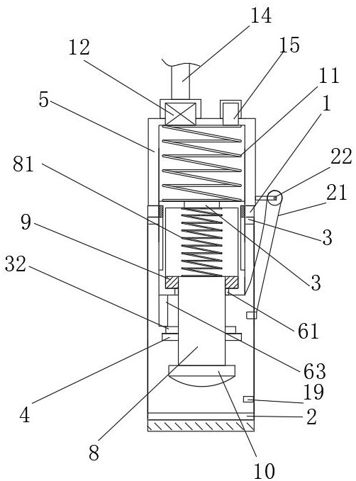
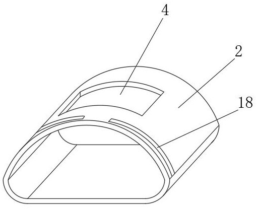
[0031] Example 1; see Figure 1-6 , a liver cross-section blood flow blocking device, comprising a fixed ring 1, the top and bottom of the inner wall of the fixed ring 1 are respectively integrally formed with an upper limit sleeve 3 and a lower limit sleeve 2 for passing through the latex tube, and a bottom of the upper limit sleeve 3 The center of the center and the top of the lower limit sleeve 2 are respectively provided with a first through groove 32 and a second through groove 4, the center of the top of the fixed ring 1 is fixedly connected with a closed pipe 5, and the inside of the closed pipe 5 is slidingly connected with a movable pipe along the vertical direction 6. The center of the top of the upper limit sleeve 3 and the center of the top of the fixed ring 1 are respectively provided with a first through hole 31 and a second through hole, and the bottom of the movable pipe 6 passes through the first through hole 31 and the second through hole and extends to the up...
Embodiment 2
[0032] The difference between Embodiment 2 and Embodiment 1 is that a pipe joint 12 is fixedly connected to the top of the closed pipe 5 and close to the front, and a check valve is arranged inside the pipe joint 12, and the device can fill the closed pipe 5 with an air pump. Inject gas to increase its internal pressure, and then achieve the purpose of pushing the movable pipeline 6, instead of the traditional working method of fixing the latex tube by twisting a screwdriver or using surgical forceps.
Embodiment 3
[0033] The difference between embodiment 3 and embodiment 2 is; please refer to Figure 1-3 , the diameter of the slide rod 8 is smaller than the inner diameter of the movable pipe 6, and the top of the slide rod 8 is fixedly connected with a piston 9 that fits the inner wall of the movable pipe 6, so that the internal air pressure of the movable pipe 6 can push the slide rod 8 to slide downward, The bottom of the movable pipe 6 is provided with an outlet for passing through the slide rod 8, and the outlet is fixedly connected with a sealing ring 61 attached to the surface of the slide rod 8, and the diameter of the first through hole 31 and the second through hole is the same as that of the movable pipe 6. Similarly, the center of the left and right sides of the movable pipeline 6 is provided with a limit groove 62 along the vertical direction, and a limit block 16 is integrally formed on the inside of the second through hole and at a position corresponding to the limit groove...
PUM
 Abstract
Description
Claims
Application Information
 - R&D
- Intellectual Property
- Life Sciences
- Materials
- Tech Scout
- Unparalleled Data Quality
- Higher Quality Content
- 60% Fewer Hallucinations
Browse by: Latest US Patents, China's latest patents, Technical Efficacy Thesaurus, Application Domain, Technology Topic, Popular Technical Reports.
© 2025 PatSnap. All rights reserved.Legal|Privacy policy|Modern Slavery Act Transparency Statement|Sitemap|About US| Contact US: help@patsnap.com


