
Automatic joint calibration device and method for laser radar and camera

A lidar and joint calibration technology, applied in computer parts, character and pattern recognition, image data processing, etc., can solve the problems of limited calibration range, high price of robotic arms, limited calibration range, etc. Accurate vertex coordinates and large calibration range

Pending Publication Date: 2022-04-19
CETHIK GRP
View PDF2 Cites 2 Cited by
  • Summary
  • Abstract
  • Description
  • Claims
  • Application Information

AI Technical Summary

Problems solved by technology

In this method, the mechanical arm controls the calibration equipment to move the sampling point, and the position of the calibration plate remains unchanged, resulting in a limited calibration range, and the price of the mechanical arm is relatively high.
[0005] To sum up, the traditional calibration method in the prior art uses a calibration board, which has a high degree of manual participation. It is necessary to manually move the calibration board, manually select or use an algorithm to automatically detect feature points, and the calibration process is cumbersome and has a large workload and a low degree of automation.
Use the robotic arm to change the position of the lidar and camera, collect calibration samples, and improve the degree of automation, but the range of motion of the robotic arm is limited, the calibration range is limited, and the price is expensive. The cost of calibration increases.
The calibration method of the fusion inertial navigation system needs to be carried out under motion conditions, and is easily affected by light and scenes

Method used


Image

  • Automatic joint calibration device and method for laser radar and camera
  • Automatic joint calibration device and method for laser radar and camera
  • Automatic joint calibration device and method for laser radar and camera

Examples


Embodiment Construction

[0079] The following will clearly and completely describe the technical solutions in the embodiments of the application with reference to the drawings in the embodiments of the application. Apparently, the described embodiments are only some, not all, embodiments of the application. Based on the embodiments in this application, all other embodiments obtained by persons of ordinary skill in the art without making creative efforts belong to the scope of protection of this application.

[0080]It should be noted that when a component is said to be "connected" to another component, it can be directly connected to the other component or there can also be an intervening component; when a component is said to be "fixed" to another component, it can Can be fixed directly to another component or there can also be a centered component.

[0081] Unless otherwise defined, all technical and scientific terms used herein have the same meaning as commonly understood by one of ordinary skill i...


PUM


Abstract

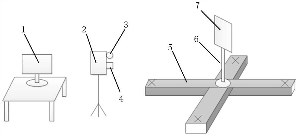
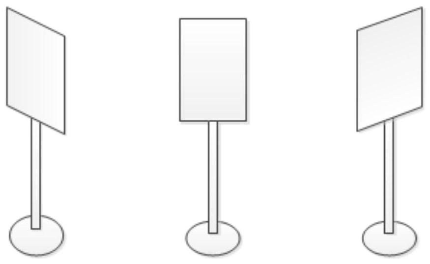
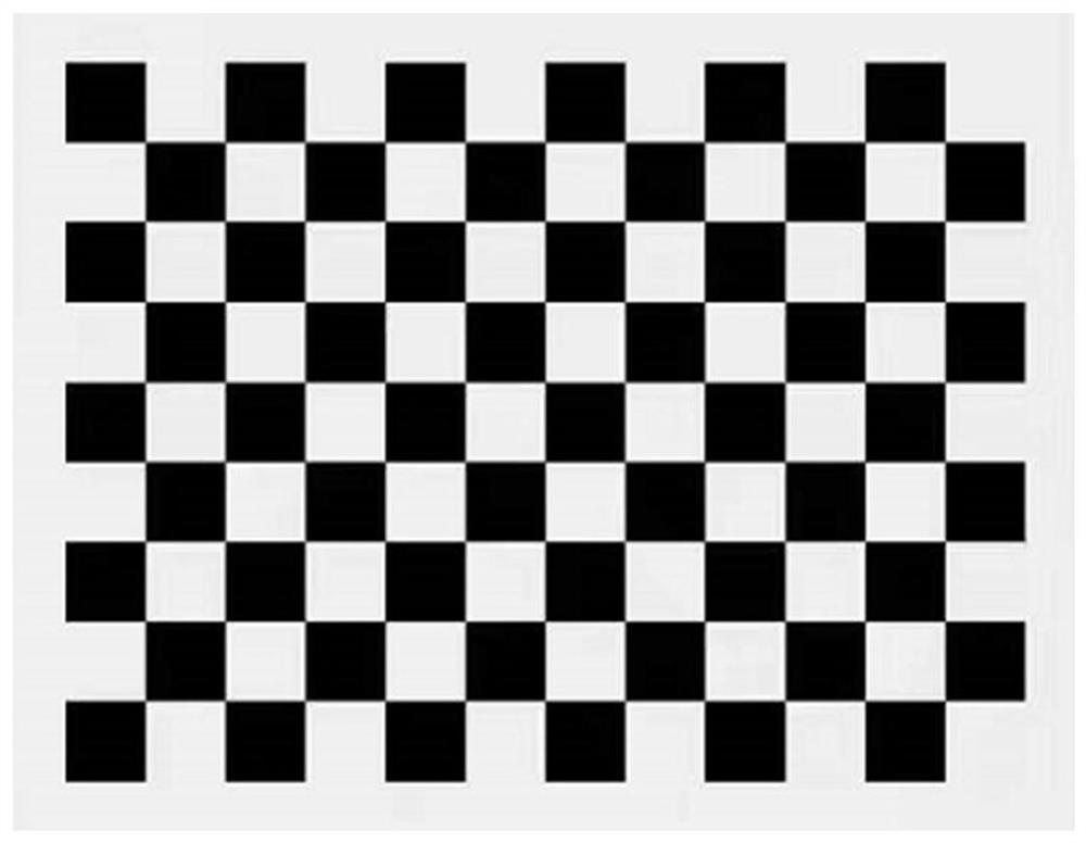
The invention discloses an automatic joint calibration device and method for a laser radar and a camera, and the method comprises the steps: controlling a movable track to move, enabling a rotatable support to be located at a preset point position, and controlling the rotatable support to change the rotation posture, so as to enable a moving part to change the direction. Acquiring image frame data and point cloud frame data in each direction of the moving part until a preset number is acquired; performing camera internal reference calibration based on the acquired image frame data; pixel coordinates of four vertexes on the outmost periphery of the calibration plate are obtained through calculation based on image frame data; point cloud calibration points are extracted to obtain final point cloud coordinates of four vertexes on the outermost periphery of the calibration plate; solving the transformation relation between the pixel coordinates of the four vertexes on the outermost periphery of the calibration plate and the final coordinates of the point cloud, obtaining a rotation matrix and a translation matrix, and completing the joint calibration of the laser radar and the camera. According to the invention, convenient, rapid and high-precision linkage calibration of the laser radar and the camera is realized.

Description

technical field [0001] The present application belongs to the technical field of equipment joint calibration, and in particular relates to an automatic joint calibration device and method for a laser radar and a camera. Background technique [0002] In the fields of mobile robots, autonomous driving, assisted driving, and environmental perception, it is difficult for a single sensor to meet the perception needs of complex environments. Multi-sensor fusion algorithms have become the mainstream algorithm at present, and the information collected by multiple sensors is fused to complement each other. The premise of improving the accuracy of multi-sensor fusion algorithm is to solve the time synchronization and space synchronization between sensors, where the space synchronization is the joint calibration between the sensors. Joint calibration is divided into two parts: internal reference calibration and external reference calibration. The internal reference calibration is the ...

Claims


Application Information

Patent Timeline
Patent Type & Authority Applications(China)
IPC IPC(8): G01S7/497G06T7/80G06V10/77
CPCG01S7/497G06T7/80G06F18/2135
Inventor 龚方徽乔宝华程坤詹兴样王方瑞董帅
Owner CETHIK GRP
Learn More