Chip welding spot structure, preparation method thereof and packaging structure

A technology of solder joints and chips, applied in semiconductor/solid-state device manufacturing, electrical components, electric solid-state devices, etc., can solve problems such as short-circuiting and affecting chip performance, achieve the effect of preventing short-circuiting and improving packaging yield

Pending Publication Date: 2022-04-19
CHIPMORE TECH CORP LTD +1
View PDF0 Cites 0 Cited by
  • Summary
  • Abstract
  • Description
  • Claims
  • Application Information

AI Technical Summary

Problems solved by technology

In this bonding process, each solder joint in the chip and each pin on the substrate circuit need to be pressed into a eutectic structure under high temperature

Method used


Image

  • Chip welding spot structure, preparation method thereof and packaging structure
  • Chip welding spot structure, preparation method thereof and packaging structure
  • Chip welding spot structure, preparation method thereof and packaging structure

Examples


Embodiment Construction

[0030] In order to make the purposes, technical solutions and advantages of the embodiments of the present invention clearer, the technical solutions in the embodiments of the present invention will be clearly and completely described below with reference to the accompanying drawings in the embodiments of the present invention. Obviously, the described embodiments These are some embodiments of the present invention, but not all embodiments. The components of the embodiments of the invention generally described and illustrated in the drawings herein may be arranged and designed in a variety of different configurations.

[0031] Thus, the following detailed description of the embodiments of the invention provided in the accompanying drawings is not intended to limit the scope of the invention as claimed, but is merely representative of selected embodiments of the invention. Based on the embodiments of the present invention, all other embodiments obtained by those of ordinary ski...


PUM


Abstract

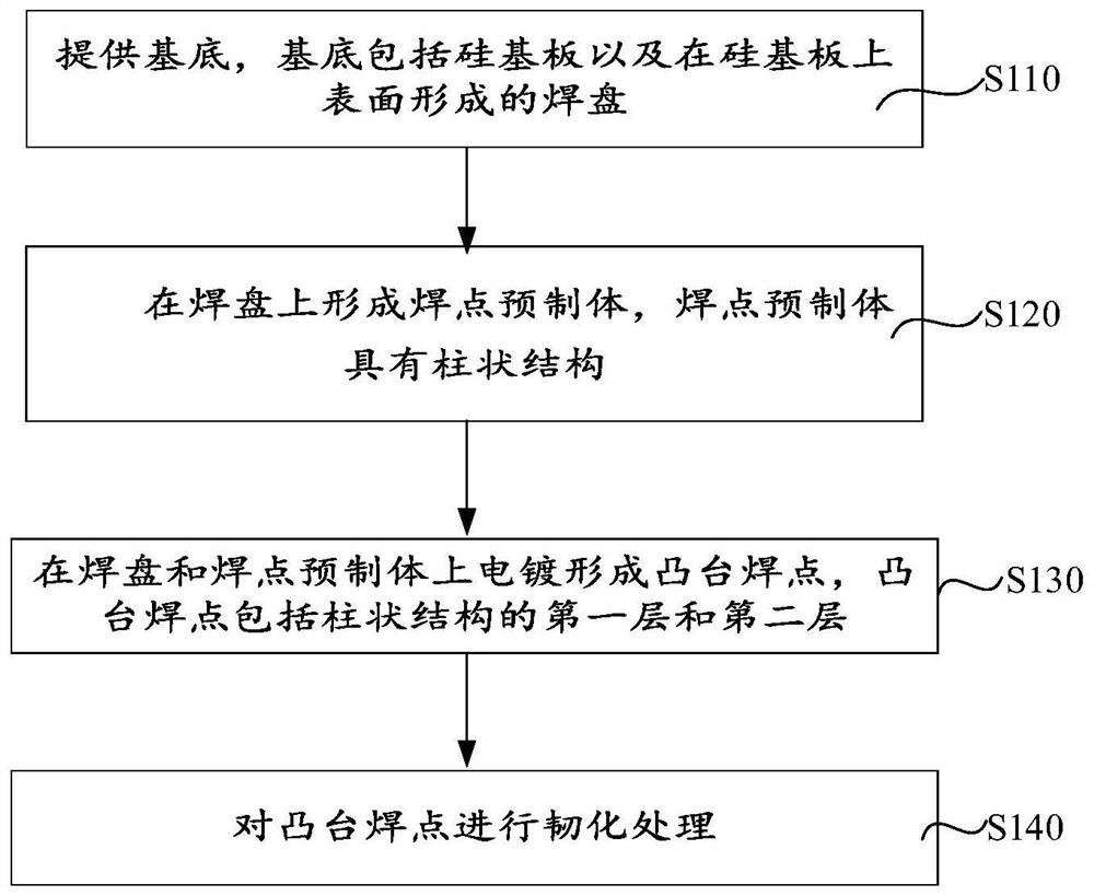
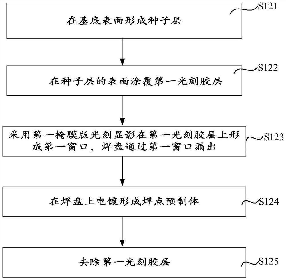
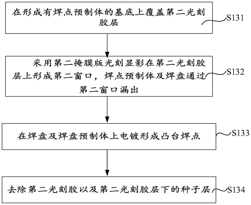
The invention discloses a chip welding spot structure, a preparation method thereof and a packaging structure, and relates to the technical field of electronic components, and the preparation method of the chip welding spot structure comprises the steps that a substrate is provided, and the substrate comprises a silicon substrate and a bonding pad formed on the upper surface of the silicon substrate; forming a welding spot prefabricated body on the bonding pad, wherein the welding spot prefabricated body has a columnar structure; a boss welding spot is formed on the welding pad and the welding spot prefabricated body through electroplating, the boss welding spot comprises a first welding table and a second welding table which are of a columnar structure, the first welding table and the second welding table are arranged in a stacked mode in the extending direction of the columnar structure, and the sectional area of the first welding table is smaller than that of the second welding table. According to the chip welding spot structure, the preparation method thereof and the packaging structure provided by the invention, short circuit between the two welding spots during packaging can be prevented, so that the packaging yield of the chip is improved.

Description

technical field [0001] The invention relates to the technical field of electronic components, in particular, to a chip solder joint structure, a preparation method thereof, and a packaging structure. Background technique [0002] With the increase in the density of integrated circuits, the packaging technology of chips is becoming more and more diversified. Because the flip chip packaging technology has the advantages of reducing the size of the chip package and shortening the signal transmission path, it has been widely used in the field of chip packaging. Flip chip packaging technology, also known as "flip chip packaging" or "flip chip packaging method", flip chip packaging technology is to bond the bare die to the substrate in a surface-down manner. The specific process is that bumps are formed on the surface of the chip, and then the chip is turned over to electrically and mechanically connect the plurality of bumps on the chip to the pins on the circuit substrate throug...

Claims


Application Information

Patent Timeline
IPC IPC(8): H01L21/60H01L23/488
CPCH01L24/11H01L24/13H01L24/81H01L2224/111H01L2224/1302H01L2224/812H01L2224/13H01L2224/81H01L2224/11
Inventor 孙轶
Owner CHIPMORE TECH CORP LTD
Why Eureka
Try Eureka