Fixing mechanism for battery of electric bicycle

A technology of electric bicycles and fixing mechanisms, applied in the field of electric vehicles, can solve the problems of battery removal, difficulty in use, short circuit, etc., and achieve the effect of convenient disassembly and assembly

Pending Publication Date: 2022-04-19
深圳市龙廷科技有限公司
View PDF0 Cites 0 Cited by
  • Summary
  • Abstract
  • Description
  • Claims
  • Application Information

AI Technical Summary

Problems solved by technology

[0003] Common batteries used for electric bicycles are generally installed with a fixing mechanism at a suitable position of the electric bicycle when fixing, and a chute is opened on one side of the battery. By aligning the battery with the fixing mechanism, the inside of the fixing mechanism The slide bar of the slide bar corresponds to the chute on the side of the battery, and can be fixed by inserting the battery. However, in order to fix the battery tightly after installation, the clamping connection between the slide bar and the chute is generally tight. When the battery needs to be disassembled At the same time, due to the tight fixation, not only does it take a lot of force to remove the battery, but also the direction of the force must be the same as the battery installation direction to pull it out smoothly. Forced pulling out is likely to cause damage to the battery case, and the force intensity

Method used


Image

  • Fixing mechanism for battery of electric bicycle
  • Fixing mechanism for battery of electric bicycle
  • Fixing mechanism for battery of electric bicycle

Examples


Embodiment Construction

[0028] The following will clearly and completely describe the technical solutions in the embodiments of the present invention with reference to the accompanying drawings in the embodiments of the present invention. Obviously, the described embodiments are only some, not all, embodiments of the present invention. Based on the embodiments of the present invention, all other embodiments obtained by persons of ordinary skill in the art without making creative efforts belong to the protection scope of the present invention.

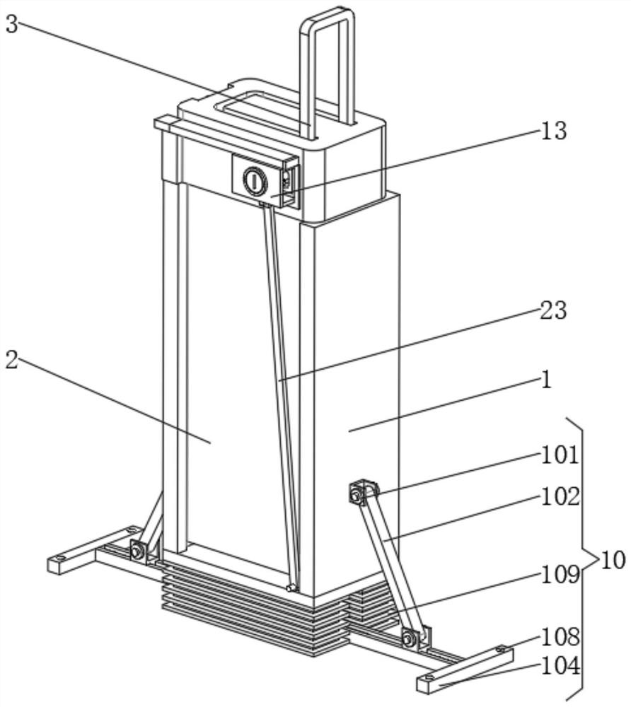
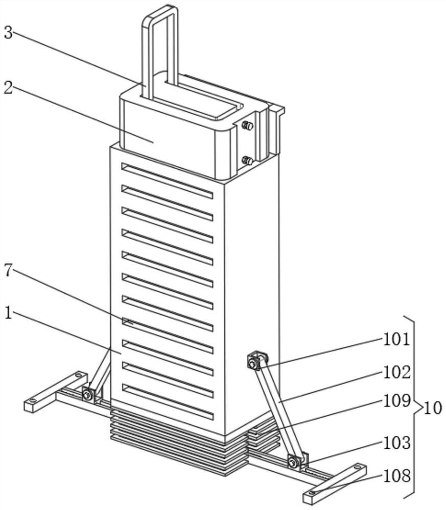
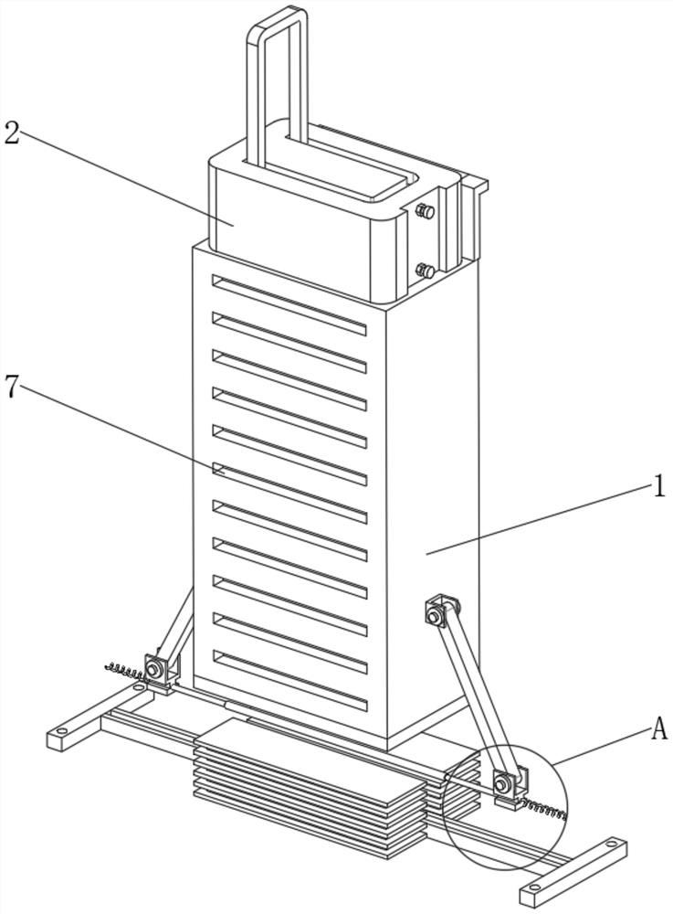
[0029] Such as Figure 4 and Figure 5 as well as Figure 6 and Figure 7 As shown, in the embodiment of the present invention, a fixing mechanism for an electric bicycle battery includes a fixing base 1 and a battery 2, an extension rod 11 is fixedly installed on the left side of the top end of the fixing base 1, and a guide rail is fixedly installed on the top end of the extension rod 11 12. The right end of the side of the battery 2 is provided with a ch...


PUM


Abstract

The invention belongs to the technical field of electric vehicles, and discloses an electric bicycle battery fixing mechanism which comprises a fixing seat and a storage battery, an extension rod is fixedly mounted on the left side of the top end of the fixing seat, a guide rail is fixedly mounted at the top end of the extension rod, and a charging port is formed in the right end of the side face of the storage battery. And a protective cover is arranged on the front surface of the fixed seat. The reset spring is compressed, the movable rod at the bottom end of the protective cover deflects towards the left side, the overall length of the movable rod is not changed, the other end of the movable rod and the movable plate can rotate relatively, and meanwhile the movable plate can only move up and down relative to the limiting groove, so that when the protective cover moves towards the left side, the movable plate can move up and down. The movable plate can be driven by the movable rod to move upwards, at the moment, the storage battery located above the movable plate can be popped out, the pre-dismounting state is achieved, dismounting can be completed by lifting upwards, dismounting with too large force is avoided, and therefore the advantage of convenient dismounting is achieved.

Description

technical field [0001] The invention belongs to the technical field of electric vehicles, in particular to a fixing mechanism for electric bicycle batteries. Background technique [0002] An electric bicycle refers to a vehicle that uses a battery as an auxiliary energy source on the basis of an ordinary bicycle, and is equipped with operating components such as a motor, a controller, a battery, a handlebar, and a display instrument system. Among the many components of an electric bicycle, the battery is It can be used as the main component of electric bicycles. Commonly used batteries for electric bicycles are also called batteries. Batteries are on-board energy sources that provide energy for electric vehicles. Electric vehicles mainly use lead-acid battery combinations. In addition, nickel-metal hydride batteries and lithium-ion batteries have also been used. It has been used on some light and foldable electric bicycles. With the new national standard, electric bicycles a...

Claims


Application Information

Patent Timeline
IPC IPC(8): H01M50/242H01M50/24H01M50/244H01M50/249H01M50/264H01M50/296
CPCH01M50/242H01M50/24H01M50/244H01M50/249H01M50/264H01M50/296Y02E60/10
Inventor 任廷燕史长龙
Owner 深圳市龙廷科技有限公司
Why Eureka
Try Eureka