Municipal sign propaganda frame welding device
A welding device and propaganda stand technology, applied in auxiliary devices, welding equipment, auxiliary welding equipment, etc., can solve the problems of insecurity, affecting welding efficiency, sparks, molten beads and iron slag splashing around.
- Summary
- Abstract
- Description
- Claims
- Application Information
AI Technical Summary
Problems solved by technology
Method used
Image
Examples
Embodiment 1
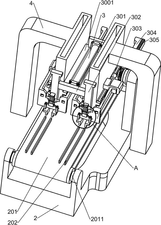
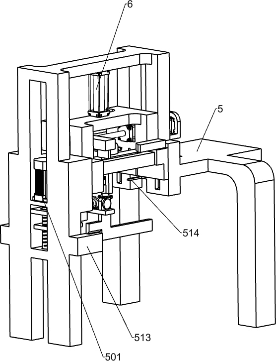
[0029] A kind of welding device for municipal logo publicity frame, such as Figure 1-11 As shown, it includes a conveyor 1, a first support frame 2, a conveyor belt 201, a first idler roller 2011, a second idler roller 2012, a storage frame 4, a second support frame 5, a feeding mechanism, a clamping adjustment mechanism and welding Mechanism, this device is equipped with a conveyor 1, the power of the conveyor 1 is a servo motor, the conveyor 1 runs intermittently, the conveyor 1 is used to transport the promotional frame, and the right side of the conveyor 1 is provided with a first support frame 2 , the first support frame 2 is used to install the conveyor belt 201, the left and right sides of the top of the first support frame 2 are respectively connected with a first idler roller 2011 and a second idler roller 2012, the first idler roller 2011 and the second idler roller 2012 A conveyor belt 201 is wound around the top, and the second roller 2012 can drive the conveyor b...
Embodiment 2
[0032] On the basis of Example 1, such as Figure 2-3 As shown, the feeding mechanism includes a No. 1 cylinder 3, a support plate 3001, a first connecting rod 301, a second connecting rod 302, a first mounting plate 303, and a clamping mechanism for propaganda frame legs. A support plate 3001, the support plate 3001 is fixed between the two material storage frames 4 and will not move, a No. 1 cylinder 3 is installed on the support plate 3001, and a first connecting rod 301 is connected to the output shaft of the No. 1 cylinder 3 , the first connecting rod 301 is in a horizontal state, and the No. 1 cylinder 3 can move the first connecting rod 301 left and right, and a second connecting rod 302 is fixed to both ends of the first connecting rod 301, and the second connecting rod 302 is vertical state, the second connecting rod 302 can move with the first connecting rod 301, and the bottom of the left side wall of each second connecting rod 302 is connected with a first mounting...
Embodiment 3
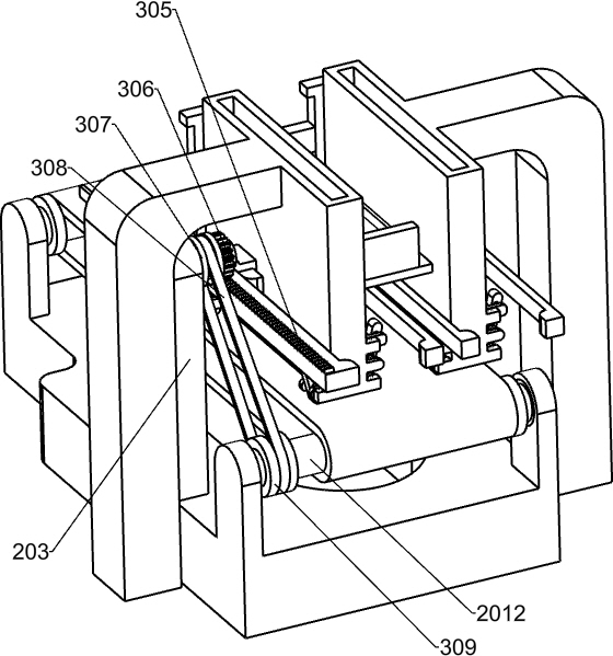
[0045] On the basis of Example 2, such as Figure 4 As shown, it also includes a first splint 202, a support column 203, a slide bar 304, a first rack 305, a first gear 306, a first pulley 307, a transmission belt 308 and a second pulley 309, and four belt pulleys are installed on the top of the conveyor belt 201. The first splint 202, every two first splints 202 are a group, the gap between the two first splints 202 of the same group can just put into a propagandist frame support leg, the front of the first support frame 2 top wall middle part is installed with A support post 203, the top of the back wall of the support post 203 is rotatably connected with a first gear 306, the first gear 306 is connected with the support post 203 through a rotating shaft, there is a gap between the first gear 306 and the support post 203, each first The right side wall of the mounting plate 303 is equipped with two sliding rods 304 symmetrically front and back, and a protrusion is arranged o...
PUM
 Abstract
Description
Claims
Application Information
 - R&D
- Intellectual Property
- Life Sciences
- Materials
- Tech Scout
- Unparalleled Data Quality
- Higher Quality Content
- 60% Fewer Hallucinations
Browse by: Latest US Patents, China's latest patents, Technical Efficacy Thesaurus, Application Domain, Technology Topic, Popular Technical Reports.
© 2025 PatSnap. All rights reserved.Legal|Privacy policy|Modern Slavery Act Transparency Statement|Sitemap|About US| Contact US: help@patsnap.com


