
Material taking and feeding device for mechanical automatic part machining

A technology for reclaiming, feeding, and spare parts, applied in conveyor objects, conveyors, transportation and packaging, etc., can solve the problems of low workpiece processing production efficiency, discontinuous feeding, high labor intensity, etc., and achieve a high degree of automation integration. , Improve production efficiency and improve the effect of processing quality

Pending Publication Date: 2022-04-22
NANJING JULONG STEEL PIPE
View PDF0 Cites 4 Cited by
  • Summary
  • Abstract
  • Description
  • Claims
  • Application Information

AI Technical Summary

Problems solved by technology

[0002] There are many pipe and shaft workpieces in the mechanical automation spare parts. In the existing batch machining process of these workpieces, due to the discontinuous feeding, the production efficiency of the workpiece processing is low, and the labor intensity is relatively high. Large, in view of this, we propose a mechanical automation spare parts processing feeding device

Method used


Image

  • Material taking and feeding device for mechanical automatic part machining
  • Material taking and feeding device for mechanical automatic part machining
  • Material taking and feeding device for mechanical automatic part machining

Examples


Embodiment 1

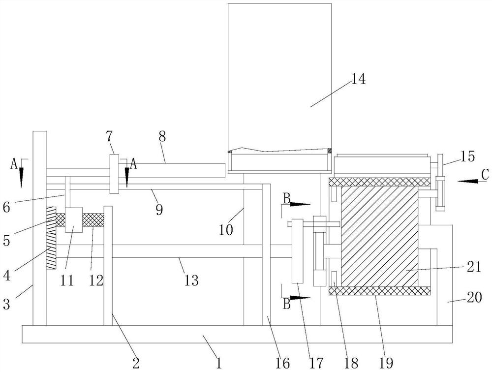
[0029] A feeding and retrieving device for mechanical automation spare parts processing, including a base 1, and also includes:

[0030] A reclaiming mechanism arranged on the base 1;

[0031] The feeding mechanism arranged on the base 1, the feeding mechanism can drive the retrieving mechanism to place the workpiece on the feeding mechanism, and the feeding mechanism adopts an intermittent operation mode to feed the workpiece;

[0032] The cleaning mechanism is arranged on the feeding mechanism, and the feeding mechanism drives the cleaning mechanism to clean the surface of the workpiece on it during the feeding process.

Embodiment 2

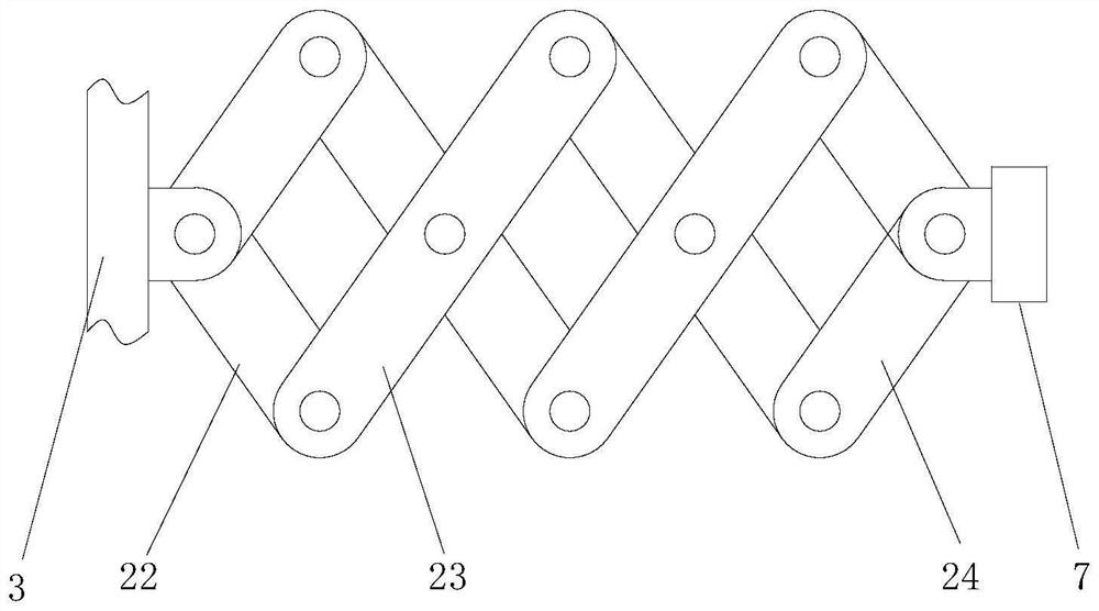
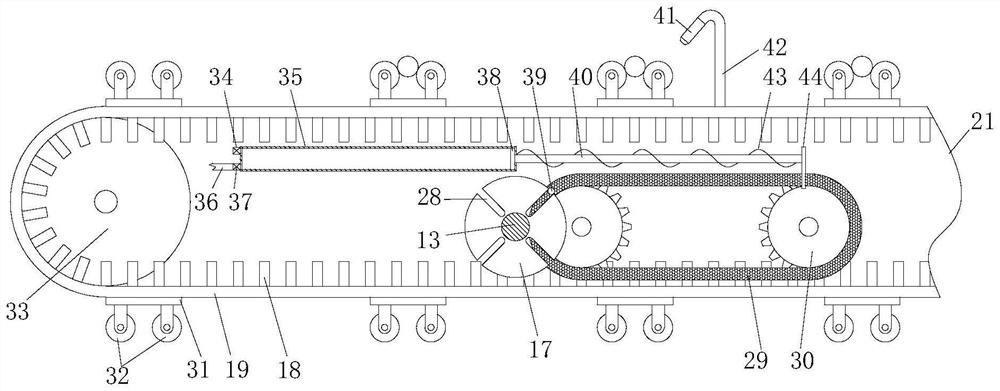
[0034] Embodiment 2 is realized on the basis of Embodiment 1: in this embodiment, the feeding mechanism includes a frame 21, and the frame 21 is fixed on the base 1 by a bracket five 20, and the side wall of the frame 21 rotates on a fixed axis Two sprockets-30 are connected, and the two sprockets-30 are connected through a chain-29 transmission, and one of the sprockets-30 is connected with the motor transmission, and the motor is fixed on the frame 21. The motor is not shown in this application. Out, the shaft 39 is connected with the fixed axis rotation on the chain one 29, and the motor drives the sprocket one 30 to make the sprocket one 30 drive the shaft rod 39 through the chain one 29 to be intermittently connected with the feeding mechanism and the cleaning mechanism respectively. The two ends of the frame 21 are connected with a roller 33 with a fixed shaft rotation, and the two rollers 33 are connected by a transmission belt 19. A plurality of supporting seats 31 are ...


PUM


Abstract

The invention relates to the technical field of machining, in particular to a mechanical automatic part machining, taking and feeding device which comprises a base and further comprises a taking mechanism arranged on the base. The feeding mechanism is arranged on the base, the feeding mechanism can drive the material taking mechanism to place the workpieces on the feeding mechanism, and the feeding mechanism feeds the workpieces in an intermittent operation mode; the cleaning mechanism is arranged on the feeding mechanism, and the feeding mechanism drives the cleaning mechanism to clean the surfaces of the workpieces on the cleaning mechanism in the feeding process. According to the mechanical automatic part machining material taking and feeding device, the cyclic automatic working state of material taking, feeding and cleaning is achieved, continuous feeding of workpieces is achieved, meanwhile, the production efficiency is improved, the automation integration degree is high, the labor intensity of workers is reduced, the surfaces of the workpieces can be cleaned, the workpiece machining quality can be improved, and the production cost is reduced. And manual cleaning treatment is not needed.

Description

technical field [0001] The invention relates to the technical field of mechanical processing, in particular to a material retrieving and feeding device for mechanical automation spare parts processing. Background technique [0002] There are many pipe and shaft workpieces in the mechanical automation spare parts. In the existing batch machining process of these workpieces, due to the discontinuous feeding, the production efficiency of the workpiece processing is low, and the labor intensity is relatively high. In view of this, we propose a feeding and retrieving device for mechanical automation spare parts processing. Contents of the invention [0003] The object of the present invention is to provide a material feeding and retrieving device for mechanical automation spare parts processing, so as to solve the problems raised in the above-mentioned background technology. In order to achieve the above object, the present invention provides the following technical solutions:...

Claims


Application Information

Patent Timeline
Patent Type & Authority Applications(China)
IPC IPC(8): B65G23/06B08B1/00B08B1/02B08B5/02B08B5/04B65G15/00B65G47/82B08B1/20
CPCB65G23/06B65G47/82B08B5/023B08B5/043B65G15/00B65G2201/02B08B1/20B08B1/12Y02P70/10
Inventor 洪航宇卢舟进赵永岫王雪松刘善燕陈英杰金博
Owner NANJING JULONG STEEL PIPE
Learn More