Mining concrete spraying vehicle

A concrete spraying and mining technology, which is applied in mining equipment, earth-moving drilling, shaft equipment and other directions, can solve the problems of difficult concrete spraying construction in mine tunnels, laborious time for pipeline layout and coiling, and inconvenient operation and operation, so as to reduce spraying. Difficulty in construction, improving work efficiency, and the effect of strong passing ability

Pending Publication Date: 2022-04-22
HUBEI TITN HEAVY MACHINERY CO LTD
View PDF0 Cites 0 Cited by
  • Summary
  • Abstract
  • Description
  • Claims
  • Application Information

AI Technical Summary

Problems solved by technology

[0002] Shotcrete is a construction method of spraying and pouring fine stone concrete with a pressure spray gun. It is often used to pour tunnel linings, walls, ceilings and other thin-walled structures or linings of other structures and protective layers of steel structures. Shotcrete is pre-mixed Good cement, sand, gravel, water and a certain amount of admixture are loaded into the jet machine, sent to the nozzle with high-pressure air to mix with the quick-setting agent, and sprayed to the surface of rock or concrete at a high speed to form , In the development of mines, the mine road is narrow and large concrete spraying vehicles cannot enter, and the existing small concrete spraying machines have no power, so it is difficult to move in the new mine road, and it is inconvenient to use large concrete spraying vehicles and super long pipelines for operation. It is labor-intensive to lay out pipelines and to collect the coils, which makes the newly developed mine road concrete spraying construction difficult and low in work efficiency

Method used


Image

  • Mining concrete spraying vehicle
  • Mining concrete spraying vehicle
  • Mining concrete spraying vehicle

Examples


Embodiment 1

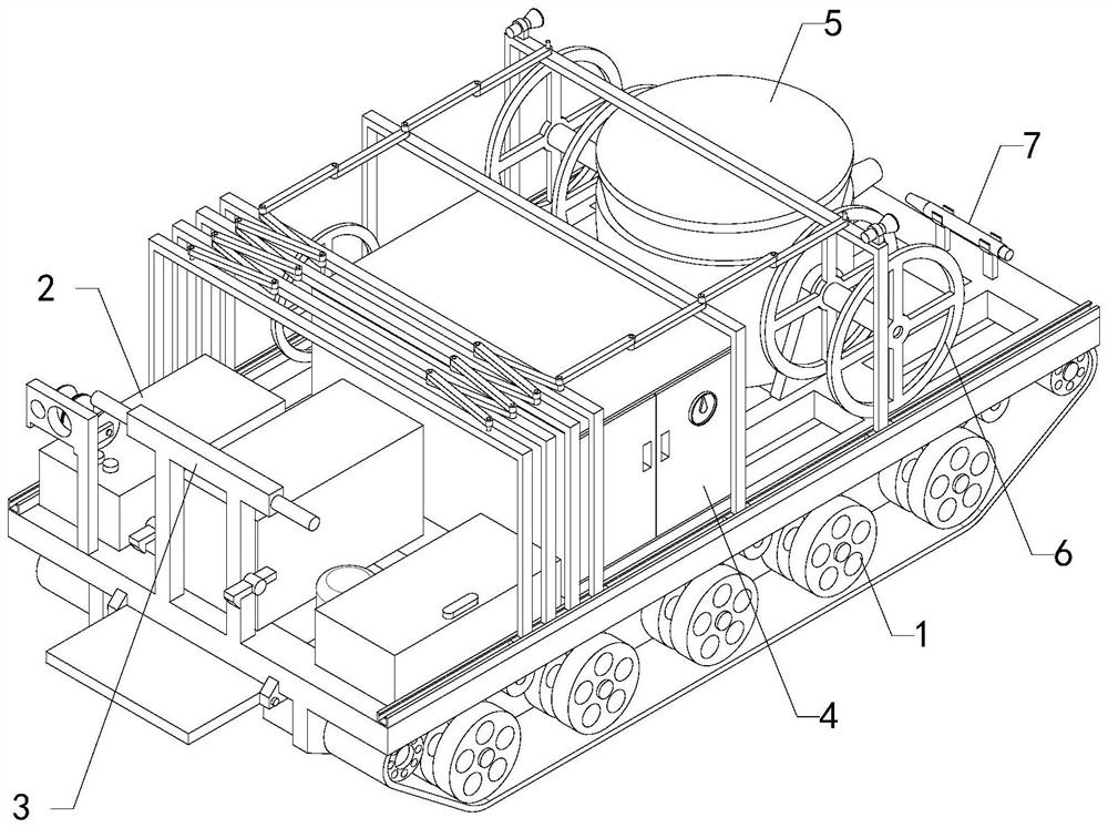
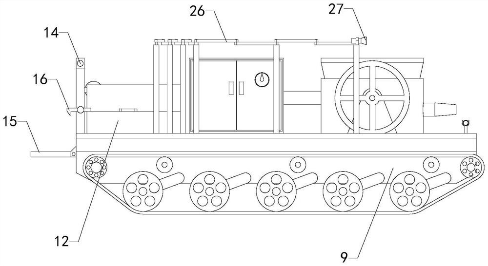
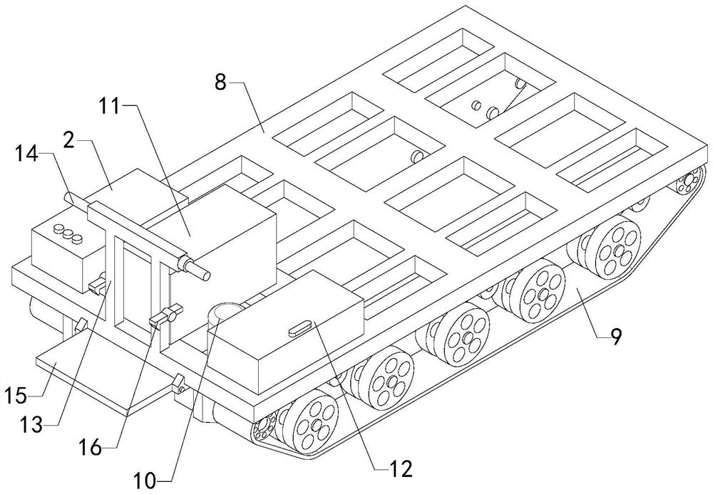
[0021] A mining concrete spraying vehicle, comprising a crawler chassis 1, a control box 2, a driver's platform 3, an air compressor 4, a spraying machine 5, a plurality of retractors 6 and a spray gun 7, the upper end surface of the crawler chassis 1 is installed with a Control box 2, a plurality of control buttons are arranged on the control box 2, the driver's platform 3 is installed in the middle part of the upper end surface rear end of the crawler chassis 1, the operating mechanism of the crawler chassis 1 is arranged on the driver's platform 3, and the air compressor 4 is installed on the track chassis 1. The middle part of the upper end surface of the chassis 1 is to the right, the jet 5 is installed in the middle of the front part of the upper end surface of the crawler chassis 1, and a plurality of retractors 6 are respectively installed on the upper end surface of the crawler chassis 1, and the plurality of retractors 6 are respectively located on the upper end surfac...

Embodiment 2

[0023]A mining concrete spraying vehicle, comprising a crawler chassis 1, a control box 2, a driver's platform 3, an air compressor 4, a spraying machine 5, a plurality of retractors 6 and a spray gun 7, the upper end surface of the crawler chassis 1 is installed with a Control box 2, a plurality of control buttons are arranged on the control box 2, the driver's platform 3 is installed in the middle part of the upper end surface rear end of the crawler chassis 1, the operating mechanism of the crawler chassis 1 is arranged on the driver's platform 3, and the air compressor 4 is installed on the track chassis 1. The middle part of the upper end surface of the chassis 1 is to the right, the jet 5 is installed in the middle of the front part of the upper end surface of the crawler chassis 1, and a plurality of retractors 6 are respectively installed on the upper end surface of the crawler chassis 1, and the plurality of retractors 6 are respectively located on the upper end surface...

Embodiment 3

[0025] A mining concrete spraying vehicle, comprising a crawler chassis 1, a control box 2, a driver's platform 3, an air compressor 4, a spraying machine 5, a plurality of retractors 6 and a spray gun 7, the upper end surface of the crawler chassis 1 is installed with a Control box 2, a plurality of control buttons are arranged on the control box 2, the driver's platform 3 is installed in the middle part of the upper end surface rear end of the crawler chassis 1, the operating mechanism of the crawler chassis 1 is arranged on the driver's platform 3, and the air compressor 4 is installed on the track chassis 1. The middle part of the upper end surface of the chassis 1 is to the right, the jet 5 is installed in the middle of the front part of the upper end surface of the crawler chassis 1, and a plurality of retractors 6 are respectively installed on the upper end surface of the crawler chassis 1, and the plurality of retractors 6 are respectively located on the upper end surfac...


PUM


Abstract

The invention relates to the technical field of concrete spraying, in particular to a mining concrete spraying vehicle which can flexibly operate in a new mine tunnel, and the working efficiency is improved. Comprising a crawler chassis, a control box, a console, an air compressor, an injection machine, a plurality of retractors and a spray gun, the control box and the console are mounted at the rear end of the crawler chassis, the air compressor is mounted on the right of the middle of the crawler chassis, the injection machine is mounted in the middle of the front of the crawler chassis, and the retractors are mounted on the crawler chassis respectively. The multiple winding devices are located on the left side of the air compressor and the left side and the right side of the injection machine correspondingly, a cable is wound on the winding device located on the left side of the air compressor, a concrete input pipe is wound on the winding device located on the left side of the injection machine, a concrete injection pipe is wound on the winding device located on the right side of the injection machine, and the air compressor is connected with the injection machine through a high-pressure air pipe. The concrete spraying pipe is connected with an output port of the spraying machine and the input end of the spraying gun.

Description

technical field [0001] The invention relates to the technical field of concrete spraying, in particular to a mine concrete spraying truck. Background technique [0002] Shotcrete is a construction method of spraying and pouring fine stone concrete with a pressure spray gun. It is often used to pour tunnel linings, walls, ceilings and other thin-walled structures or linings of other structures and protective layers of steel structures. Shotcrete is pre-mixed Good cement, sand, gravel, water and a certain amount of admixture are loaded into the jet machine, sent to the nozzle with high-pressure air to mix with the quick-setting agent, and sprayed to the surface of rock or concrete at a high speed to form , In the development of mines, the mine road is narrow and large concrete spraying vehicles cannot enter, and the existing small concrete spraying machines have no power, so it is difficult to move in the new mine road, and it is inconvenient to use large concrete spraying veh...

Claims


Application Information

Patent Timeline
Patent Type & Authority Applications(China)
IPC IPC(8): E21D11/10E21D11/40
CPCE21D11/10E21D11/40
Inventor 孙太斌
Owner HUBEI TITN HEAVY MACHINERY CO LTD
Why Eureka
Try Eureka