Polar thermoelectric power generation system

A technology of thermoelectric power generation and box body, which is applied in the direction of generator/motor, electrical components, combustion product treatment, etc. It can solve the problem of non-removable and replaceable heat conduction parts, achieve effective fixed installation and disassembly, ensure use efficiency, and reduce replacement and the cost of maintenance

Pending Publication Date: 2022-04-22
THE FIRST INST OF OCEANOGRAPHY SOA
View PDF0 Cites 0 Cited by
  • Summary
  • Abstract
  • Description
  • Claims
  • Application Information

AI Technical Summary

Problems solved by technology

[0006] The invention provides a polar temperature difference power generation system, which solves the problem that the heat conduction parts cannot be disassembled and replaced

Method used


Image

  • Polar thermoelectric power generation system
  • Polar thermoelectric power generation system
  • Polar thermoelectric power generation system

Examples


no. 1 example

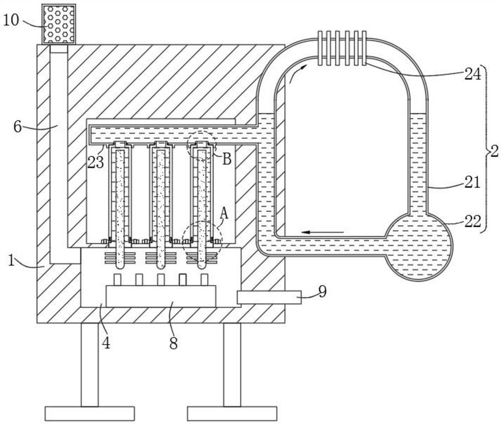
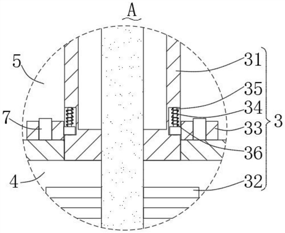
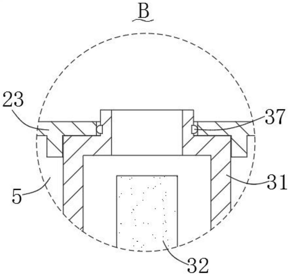
[0042] Please refer to figure 1 , figure 2 , image 3 , Figure 4 ,in, figure 1 A schematic structural diagram of the first embodiment of the polar thermoelectric power generation system provided by the present invention; figure 2 for figure 1 The enlarged schematic diagram of part A shown; image 3 for figure 1 The enlarged schematic diagram of part B shown; Figure 4 for figure 1 Schematic diagram of the exterior of the thermally conductive structure shown. Polar temperature difference power generation system, including:

[0043] A box body 1, a cooling structure 2, and a plurality of heat conduction structures 3 for heating the medium inside the cooling structure 2, wherein the cooling structure 2 is arranged on the box body 1, and the heat conduction structures 3 are installed on the One side of the cooling structure 2;

[0044] The heat conduction structure 3 includes a connecting pipe 31, on which a thermoelectric power generation assembly 32 is arranged, an...

no. 2 example

[0064] Please refer to Figure 5-6 , based on the polar thermoelectric power generation system in the first embodiment of the present invention, the second embodiment of the present invention provides another polar thermoelectric power generation system, wherein the second embodiment will not hinder the technical solution of the first embodiment Implemented independently.

[0065] Specifically, the present invention provides another polar thermoelectric power generation system with the following differences:

[0066] The box body 1 is provided with a cleaning structure 11 for cleaning the smoke and dust inside the flue exhaust duct 6, and the cleaning structure 11 includes a moving scraper 111 located below the flue exhaust duct 6 for driving the moving The scraper 111 moves the driving part 112 in the vertical direction and the magnetic block 113 for absorbing and fixing the bottom of the driving part 112. The outer side of the moving scraping part 111 is attached to the inn...


PUM


Abstract

The invention provides a polar region thermoelectric power generation system. The polar region thermoelectric power generation system comprises a box body, a cooling structure and a plurality of heat conduction structures used for heating a medium in the cooling structure, wherein the cooling structure is arranged on the box body, and the heat conduction structure is installed on one side of the cooling structure. According to the polar region thermoelectric power generation system, the heat conduction structure is arranged and used in cooperation with the cooling structure, heating treatment can be carried out on a solution medium in the cooling structure, the connecting pipe and the flow guide pipe are arranged to be in an assembling mode, free mounting and dismounting of the connecting pipe and the flow guide pipe can be achieved, and when the heat conduction structure breaks down, the heat conduction structure cannot break down. The heat conduction structure can be independently detached for maintenance or direct replacement, a traditional integrated structure is changed, the heat conduction structure is more flexible and more convenient to use, the use efficiency of the heat conduction structure is guaranteed, and the replacement and maintenance cost is reduced.

Description

technical field [0001] The invention relates to the field of power generation, in particular to a polar temperature difference power generation system. Background technique [0002] Power generation refers to the conversion of water energy, thermal energy of fossil fuels, nuclear energy, solar energy, wind energy, geothermal energy, ocean energy, etc. into electric energy by means of a power generation device. At the end of the 20th century, fossil fuels were mostly used for power generation, but the resources of fossil fuels are not many and are gradually being exhausted. More and more renewable energy has been used to generate electricity. [0003] Thermoelectric power generation belongs to the category of power generation technology. It is a kind of temperature difference between high and low temperature heat sources, using low boiling point working fluid as the circulating working medium, and using high temperature heat source to heat and evaporate the circulating workin...

Claims


Application Information

Patent Timeline
Patent Type & Authority Applications(China)
IPC IPC(8): H02N11/00F23J3/02
CPCH02N11/00F23J3/02
Inventor 刘蕾陈凤云彭景平葛云征刘伟民
Owner THE FIRST INST OF OCEANOGRAPHY SOA
Why Eureka
Try Eureka